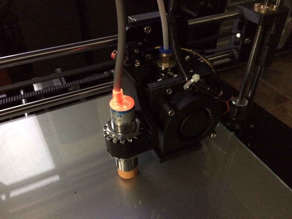
Mount for an 8mm inductive sensor designed to fit a Tronxy P802E.
A description on firmware set up and calibration is posted below the part description here.
Offsets are X-55, Y-26. This design allows for mounting the sensor in close proximity to the bed as aluminum used in the construction of the heated bed reduces the design range of the sensor considerably. With this design I am able to use the 8mm sensor with a glass build plate on the original supplied bed with minor allowances for it to clear the print. The design also conforms to physical requirements of the carriage assembly my Tronxy P802E came with. Additionally use of angles and curves allows it to be printed without the requirement for support material.
I am reasonably convinced any combination of sensor be it PNP, NPN, NO or NC can be wired into a controller by use of various settings, voltage dividers, mosfets and/or diodes to make them operable. For various reasons in my application I elected to use the following sensor:
LJ18A3-8-Z/BX 8mm Approach Sensor Inductive Proximity NPN NO Switch DC 6-36V LW
For my application the sensor is powered from the main 12VDC supply voltage to ensure operation within the sensor's design range. The sensor offers sufficient sensitivity to operate with an aluminum bed and will allow for the use of a glass build plate. On my Tronxy P802E, a 5VDC active-lo signal is supplied via the board's own Z end stop header pin to the Z end stop frame mounted micro switch and signal is sent through the NO micro switch to the Z end stop ground pin of a Melzi 2.0 "TRONXY" variant silk screened as board version 5. On measurement it appears this particular inductive sensor uses an internal pull up which in the untriggered state pulls the sensor line up to the supplied voltage. In this case the supplied 12VDC! To provide reverse current protection for this pull up state I installed a diode on the signal line thus the Z end stop input sees only it's own 5 volt active-lo signal which is pulled to ground when triggered. By using this arrangement the sensor behaves in the same manner as the supplied micro switch. Through wiring the sensor in parallel to the existing micro switch (diode protected sensor signal line to Z end stop switch input line) and setting the micro switch slightly lower than the sensor trigger point I was able to create a mechanical safety end stop should the inductive sensor fail. The micro switch is trigger at the point the extruder makes contact with the build plate thus mitigating possible serious damage from a unlikely sensor fault.
You will need to set up auto bed leveling in your firmware. I felt I was unable to satisfactorily configure the factory supplied Repetier firmware through the user interface to enable auto bed leveling to the degree I wish to tailor it. You may have reasonable success but I wanted control at the firmware level to optimize my settings thus requiring a complete revision to my printers firmware.
In my case my Melzi board required a more versatile Sanguino boot loader installation and in order to get things working the way I wanted, I configured a version of Marlin. Before embarking down the road of auto bed leveling I recommend investigating whether you are prepared to possibly go through the process of changing and modifying your firmware and potentially programming the bootloader with an ISP as the "out of the box" solution appears to be quite limiting. The benefits may outweigh the cost but for prints with long dimensions adhered to the build plate it is almost an indispensable requirement to ensure success.
Set up guide:
The following posts will go through the process in phases. Depending on what the TRONXY printer you received came with and what you wish to achieve these phases may or may not apply. Understand I have hands on experience only with P802E arriving with a Melzi 2.0 controller and Repetier firmware. Although much of the information will be adaptable to other applications, this is system I was directly working on.
The phases are as follows:
1 Uploading a bootloader (optional if your board will accept uploading firmware to it)
2 Installing new firmware
3 Installing the sensor
4 Auto level firmware adjustments in configuration.h settings
5 Calibrating the sensor
6 Custom Start/End GCode
7 Things I inevitably forgot to think of...
Before getting into the discussion it is important to note that as a result of developments in the Arduino IDE version compatibility issues pose many challenges. I will attempt to ensure that I mention what version of the IDE is being used when working with firmware. In some instances using the wrong version for which the firmware was written will fail to compile. Other instances may pose communication issues while others will pose challenges in terms of where to import libraries. Welcome to the open source (free software) world.
Lastly I offer this information as just that; information. I hold no responsibility or accountability for any damage you may do to yourself or your equipment by utilizing or applying this "information" in any way. The possibility exists to brick, burn or otherwise completely destroy your hardware as well as having your printer go absolutely haywire and self destruct into a pile of useless rubble. It may even elect to go terminator on your neighbors cat. PROCEED AT YOUR OWN RISK!
1 Uploading a bootloader (optionally required if your board will not accept uploading firmware to it)
Before even considering the boot loader you have to ask yourself whether you are able to achieve your auto level requirements using the existing firmware the printer was shipped with. If the answer is no then you have to see if your printer will accept uploaded code. My recommendation here is to obtain a copy of the original firmware your printer came with. At startup the printer display should give you an indication of what's installed. Although not absolutely necessary, having the original firmware will allow you to test the ability to program your controller and recover your printer back to factory settings should you wish to.
In my case my printer did not appear to have a boot loader that would communicate appropriately with any versions of Arduino IDE I attempted to connect to it. I investigated whether there were communication issues as a result of a clone FTDI USB to Serial adapter. Fortunately the Melzi board supplied with my printer had a legitimate FTDI chip. If you have a clone it is usable as well but you will have to investigate drivers and possible temporary bricking issues. WHQL drivers were released that can pose problems with communication and recoverable bricking issues with these CH340 clone chips. Google is your friend here but in my instance my board has the FTDI brand chip so uploading firmware came down to having a suitable boot loader.
The boot loader hardware file I use is Sanguino for ATmega1284p @ 16mhz. Visually looking at your board you should be able to identify this processor and the frequency on the oscillator. After installing Adruino IDE version 1.8.2. you will need to follow the instruction here to install Sanguino. http://dustsreprap.blogspot.ca/2015/06/better-way-to-install-sanguino-in.html. Now you will require an ISP. In my case I utilized an older Arduino Duemilanove. This is what I had and is not to say it's the best or only ISP around but I know this worked.
POINT OF NO RETURN! if you decide you need a boot loader installed understand that there are risks that you may not recover from. The boot loader is your controllers window to the outside world. Failure of the boot loader installation may brick your board. PROCEED AT YOUR OWN RISK! BE CERTAIN YOU WANT AND NEED THIS AND ARE WILLING TO ACCEPT THE OUTCOME GOOD OR BAD.
Steps I went through as follows:
-Wired my Arduino as ISP to the "old wiring" scheme from the Example sketch that comes with 1.8.2 and removed the comment for this to work (not sure this is a factor but that's the way I had it wired to work with the older IDE for my tests).
-Removed all wired connections from the Melzi less end stop switch inputs. Critical!
-Uploaded the Arduino as ISP sketch to the duemilanove. (probably work with UNO etc.)
-Melzi reset jumper installed. USB power jumper moved to USB position. Connect ISP connector as per instructions in sketch between boards.
-Set board to Sanguino. Processor Atmega1284p 16mhz.
-Set Port to comm port of duemilanove.
-USB cable to duemilianove. No USB cable to Melzi.
-Burn bootloader.
It is important to note that any power to the Arduino and Melzi during this process came solely from the one USB connection to the Arduino. No other power was applied. Power went through the Adruino to the Melzi with the Melzi obtaining power through the 6 pin ISP connector from the Arduino with the USB jumper setting set on the Melzi.
2 Installing new firmware
Assuming you've already covered off requirements of Phase 1 and now have a Melzi in your Tronxy with a boot loader that will allow you to upload code through it's USB port it's time to get onto the code. Firmware comes in various flavors and Tronxy appears to have written firmware for their printers based on both Repetier and Marlin. The printer I received was supplied with Repetier and had Tronxy's version 1.6 of it. After playing around with Repetier online configuration tool I quickly came to the understanding A. I have no idea what I needed to do with end stop switch settings to get this working or B. Repetier is dead set on using max end stops for bed leveling; something the Melzi isn't conducive to do and I'm unwilling to re-invent the wheel (wheel being Tronxy P802E in this case) to make this work with max end stops. Anyway despite putting in a semi-serious effort with Repetier I abandoned that avenue and decided on Marlin. I managed to locate a auto level version written for the P802MA. Unfortunately it wasn't plug and play so I went about calibrating various bed adjustments, probe offsets and pattern settings to get what I wanted from it. It is the older V1.0 but works well and was the 90% solution so I'm not rushing to reconfigure to 1.1 just yet.
The version compiles in Arduino 1.6.9 but has issue compiling with 1.8.2 the latest version as of this writing. Rather than fixing the code I elected to try the older 1.6.9 IDE and it worked. This requires downloading the older IDE and once again adding in Sanguino support to this IDE to allow it to communicate to your Melzi with the Sanguino boot loader. Settings for communication now become those for your Melzi's port. Hardware settings remain Sanguino w/ATmega1284p @ 16mhz now set in the older IDE.
Melzi jumper settings now back to default powered by input 12V. Make shift Arduino Duemilanove ISP disconnected and sent back into retirement. Reset jumper remains installed on Melzi.
Verify-Compile-Upload.
The system should now reboot to the new firmware which can be verified by the IDE upload confirmation message and the printer display message.on startup.
3 Installing the sensor
The sensor I chose was a LJ18A3-8-Z/BX 8mm Approach Sensor Inductive Proximity NPN NO Switch DC 6-36V LW. There is conflicting information out there regarding the reliability of operation of these sensors at 5 volts which is below the minimum specified operating voltage. It appears the main reasons for people wanting to operate the sensor at 5 volts is to limit the voltage to that used in the logic level of the Melzi board thereby mitigating potential damage to the board as a result of feeding it a higher voltage. Two potential issues arise from this approach. First off it's below the sensors minimum specified design voltage and secondarily it is now putting addition load on the 5VDC supply of the Melzi to power the sensor. By utilizing the 12VDC power supply voltage both of those concerns are removed. The downside is now the sensor has 12VDC going to it and we want to make sure that isn't what's coming out.
So let's look at the behavior of the sensor. The sensor gets fed positive 12VDC on the Brown wire and negative 12VDC on the Blue wire. If we bring something metallic near the sensor it triggers and the LED illuminates. You can play with all this on the side using a 9V battery just substitute 9V for 12V in your readings. Now we have the Black signal wire we want to use to act as an input somehow to the Melzi. If we hook the positive of a voltmeter to the Black signal wire and the negative to the same Blue ground wire negative 12VDC is on; the signal wire un-tripped reveals 12VDC and virtually zero volts when tripped and the LED is lit. Switching now to ohms we see some resistance on the line when un-tripped and virtually zero resistance when tripped. Basically from this we derive that this sensor wire can be a switch to ground when tripped but with the appearance of 12VDC when un-tripped there is a condition there we don't have any use for and is detrimental to the well being of our board. Some people have suggested this voltage is the signal wire "floating" and not to be concerned with the voltage. That's all well and good but I don't want to take a chance that it's being pulled up to 12VDC so I go a step further to eliminate it altogether. We only want to allow current to flow to ground when tripped but the other part of it's operation we don't want, the 12VDC flowing out to our board so we can use a diode to allow current to flow only to ground and block the 12VDC from going out the other way. To ensure the diode is in the correct anode to cathode current flow orientation we connect it to the end of the black lead and run our tests again. If we have it right 12VDC is NEVER seen on the signal wire and the signal connects to ground when tripped. We now have created a switch to ground with no other ill side effects.
If we look at our Z end stop micro switch it has two wires. One wire, yellow on my printer, reads 5VDC when checked for voltage. The other black wire to the switch reads zero ohms when comparing readings to our boards ground. So we can deduce that either the logic of the Z end stop is held high and closing the NO switch of the micro switch takes that 5V down to ground (active-low) or we may also speculate the black wire is brought high from 5 volts provided by the yellow wire (active-high). Since the black shares ground with board this second deduction must be false as no circuit would simply feed 5V directly to board ground when the switch is closed. Active-low it would appear to be.
So going back to wiring our sensor. The signal wire with sensor activated goes to board ground and lo and behold the mirco switch black lead also goes to board ground, so if I just simply solder the diode now in series signal lead to the spade connector of the black lead we have just put a second Gucci inductive sensor switch in parallel with the micro switch that will turn
:format(webp)/https://fbi.cults3d.com/uploaders/30772521/illustration-file/69437045-7f25-4b7f-9f37-4c466c17e0f3/8mm_Inductive.JPG)

/https://preview3d-images.cults3d.com/4wkv40hkzuwt721ibduraamncmo1)


