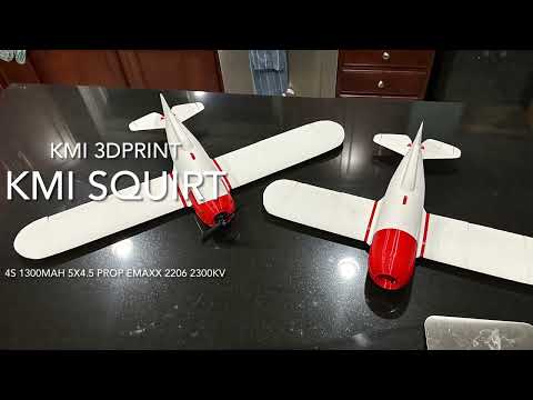
Video:
https://www.youtube.com/watch?v=mqZxRfTy3K0
Follow my channel for updates as they come!
Test AUW:
• 510g+/-
Tested power:
• Motor – Emaxx 2206– 2300kv
• Esc: 40amp
• Battery: 3-4s 1300-1800mah
• 5x4.5 prop
Other electronics
• Min 4 channel Rx
• 3 9g servos – standard 9g will fit snuggly, even might cause a slight bump, but thinner is better. You can always trim the corners down on the servo to prevent the bumps on the top side of the wing. The bumps will not effect flight.
Needed parts:
• 6x4x1000mm CG tube
• 16-20 M2.3 screws
• 450mm pushrod (x2)
Optional parts
• 6x1 pultrude – There is a slot to use from fuse 3 – 5 that you can slide this into to stiffen the tail. So far I haven’t seen it necessary but some want this.
• 3x1 pultrude – used for hstabs. Adds extra rigidity to the tail. If going for speed it is suggested.
• Landscaping flags – Wire to be used in the alignment holes. I noticed this added some extra rigidity to the walls when used. This is also best used for the aileron and elevator hinges. A pushrod will work but allows more play and if going for speed, that is not ideal.
Material built for:
LW-PLA(HT)/PLA/PETG
This is built for fuse (3-5) and wings to be printed in LW PLA. Fuse is double wall, so it is not recommended to print entirely in PETG/PLA unless you add a motor prop setup to account for the additional weight. Fuse 1 and Fuse 2 should be printed in PLA/PETG since they slide together and screw. Fuse 2 can be printed in LW and be successful, however, the additional weight in the nose with the PLA/PETG helps hit CG.
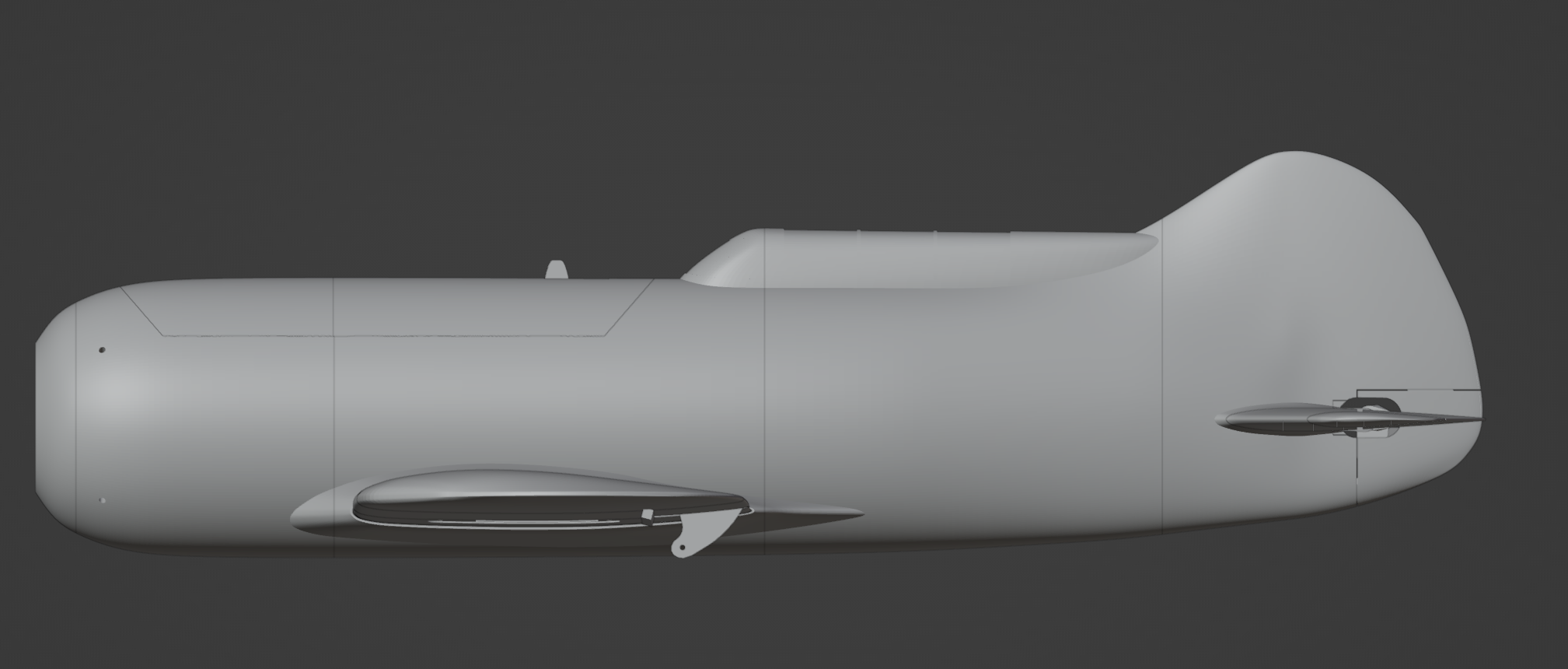
Notes:
If you need another bolt pattern for the motor mount, please contact me and I will get one for you to print
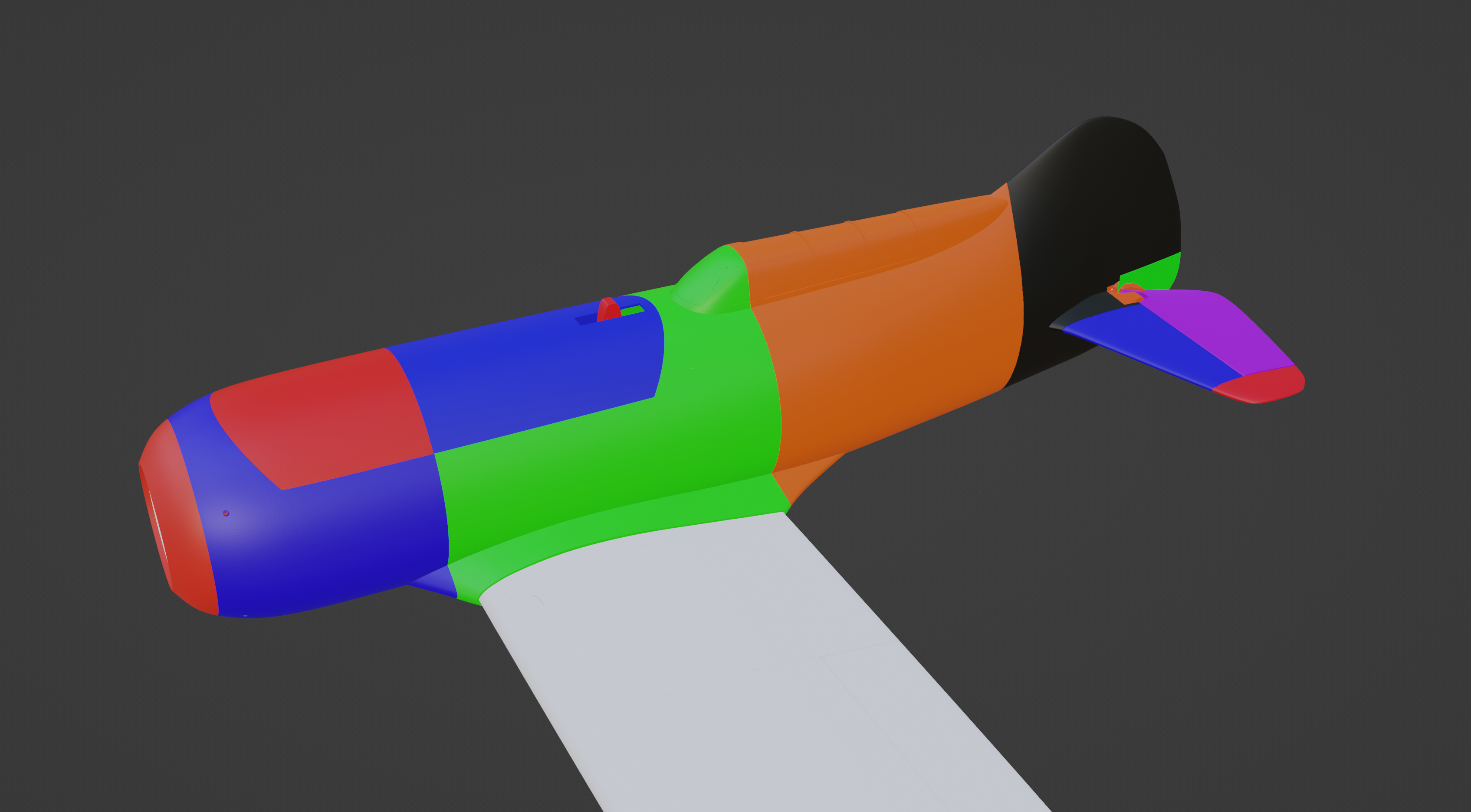
Print guide:
Folders are organized by material type.
Part
Layer height
Top later
Bottom layer
Spiral/vase mode
Infill
Material
Fuse1 .16 0 2 No 20% PETG/PLA
Fuse 2 .2 0 0 No 0% LW
Fuse 3 .2 4 0 No 0%
Fuse 4 .2 0 0 No 0%
Fuse 5 .2 0 0 No 0%
WingL 1* .2 0 2 Yes 0%
WingL 2* .2 0 2 Yes 0%
WingL 3* .2 0 2 Yes 0%
ElevatorL* .2 2 8 No 0%
AileronL* .2 2 8 No 0%
Motor plate .16 4 6 No 20% PETG
Canopy F .2 2 0 Yes 0% PETG/PLA
Canopy R .2 2 0 Yes 0% PETG/PLA
Fuse servo plate .16 4 6 No 20% PETG/PLA
Hinge anchor .16 4 6 No 20% PETG/PLA
Lock base .16 4 6 No 20% PETG/PLA
Lock .16 4 6 No 20% PETG/PLA
Tail cover .2 2 2 No 0% PETG/PLA
Wing base* .2 0 2 No 0% PETG/PLA
Wing pin (x4) .16 4 6 No 20% PETG/PLA
Servo cover (R/L) .16 4 6 No 20% PETG/PLA
Ele-horn .16 4 6 No 20% PETG/PLA
Parts marked with an (*) Should have a mirrored part with them. If it is not found, simply mirror the part on the plate.
For best results print all parts except aileron and elevators one at a time.
For best results with aileron and elevator, they should be printed side by side and trimmed after print. Make sure to pint the trailing edge toward your z seam to keep a clean surface that rotates in the wing or hstab.
Elevator Example
Post Print
Clean out all pieces as best you can. Vase mode was sacrifice for strong internal support. Clean up will happen.
Build
- Cut 1000mm tube in half for main spar. The rear support is 150mm. Not needed but does give additional support during landing to prevent the wings from squeezing in the rear.
a. The parts have been saved for the correct plate orientation. Please keep an eye out for tail-anchor and make sure it is as flush to the plate as possible.
Fuse
- For me it was easier to print the fuse parts in order starting from the rear. Using the landscaping flag wire, I was able to hold them in position until ready to glue.
- Using the pin guides, you can either use landscaping flag or simply use a little of your filament to guide them together when gluing.
a. Make sure to dry fit all parts.
- Tail cover – your bed must be level. The foot print of this touching the plage is very small but will print if your adhesion is good and bed is leveled.
Wings
1. Using the CF tubes insert them through wing base and place wing 1 on top. This will hold them aligned while gluing. Wing 1 may be off by about .5mm. Do not worry, this is expected with the expanding foam over other filament types.
You can remove the small CF part and keep the longer in place. Slide wing 2 in place and test fitment. Once happy, glue them together.
2. With wing 3 glued to 2, put a landscaping wire down the aileron hinge hole and insert into the hole on the tab of wing 3.
a. On wing 3 there is a tab end. Do not cut this off. I left this a bit thick so that people would pay more attention to it. This is to cover the top of Wing 2 when glue together. You should shave this a bit once glue together fir better aileron fitment.
3. While this is in place you can use the aileron hinge and a small portion of the CF to align wing4 into place.
Tail
1. There is an alignment hole on the hstab that can be used to ensure the right alignment. If using a pultrude, slide the pultrude into the hstab, and slide into place. Make sure the top of the hstab is aligned to the top of the fuse 5 hstab hub.
a. Repeat for opposite side.
2. Glue the elevator hinge anchor in place. There is a joiner that holds the two pieces together. This goes along the top of the fuse.
3. Using landscaping wire, right through one elevator until you get to the hinge opening. Place onto anchor and slide all the way through. This will hold the first elevator in place.
a. Place the second elevator in place and slide the landscaping wire all the way through. This should hold both elevators in place.
4. With elevators in place, you can glue hstab 2 in place. There should be a hinge hole to use. If using a pultrude, there should be a hole for a small portion of the pultrude to align hstab2 in place.
a. Either way, make sure the top of hstab2 is aligned with the top of hstab2.
5. With the elevators in place, take the elevator hinge and put the pushrod in place. You can slide the pushrod into fuse 6 and into the pushrod support.
6. You will notice two slots on the elevator hinge. The larger opening goes toward the fuse and will slide down the inside of the elevators. Push all the way down as far as it can go. As you are gluing, make sure that the elevators are aligned. There is enough room to fit the elevators and make small adjustments to ensure they are parallel. For best results align the trailing edge of the one elevator to the trailing edge of the hstab2 on the same side. Glue put a dab of glue and then hit it with activator to ensure it is secure. Once that single elevator is secure, repeat steps for second elevator.
a. Although the movement can make it seat unaligned, it is small enough to not drastically effect flight.
Assembly
As you will notice the wings are detachable. This makes it easier for replacement, transport and more. You can glue them together If you are more comfortable.
- Screw servos into the servo cover. There are 6 total