Skip to content

Anycubic i3 Mega optical endstops for z-level

Advertising
Advertising
?
Creation quality: 0.0/5 (0 votes)
Evaluation of members on the printability, utility, level of detail, etc.

  • 440 views
  • 4 downloads
  • 1 collection

License
3D design format
STL Folder details Close
  • i3_Mega_Screw_fix_1.stl
  • i3_Mega_Screw_fix_2.stl

Learn more about the formats

Publication date 2023-11-09 at 12:47
?
Published to Thingiverse on: 2019-10-11 at 23:58
Design number 1567361

3D printer file info

3D model description

Anycubic i3 Mega optical endstops for z-level

Da die einfachen Microtaster des i3 Mega für das z-Leveling aus meiner Sicht unzureichend sind und das Druckbett immer wieder neu eingestellt werden muss, hab ich die Z-Endstops mit Lichschranken ausgestattet.

Folgendes wird für die Installation benötigt:

  • Marlin 1.1.9 Firmware
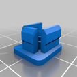
  • ausgedruckte Teile i3 Mega Screw fix 1 und 2 (Infill 100%)
  • 5VDC Stromversorgung (Ich nutze einen Spannungswandler 12VDC -> 5VDC, welcher direkt am internen Netzteil des Anycubic angeschlossen ist.)
  • 2 x original Anycubic i3 Mega Kontaktschalter
  • 2 x Lichtschranke für Arduino

https://eckstein-shop.de/10mm-Lichtschranke-Photoelectric-Infrarot-Zaehler-Counter-Sensor-Modul?curr=EUR&gclid=EAIaIQobChMIi_XD6I6V5QIViOJ3Ch0Rlw2EEAQYBCABEgLg9_D_BwE

Installation:

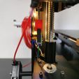
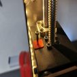
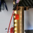
  1. Ausgedruckte Teile i3 Mega Screw fix 1 und 2 an der Levelscharaube des Druckers anbringen (Bild 3 und 4).
  2. Lichtschrankenbereich von der restlichen Platine abtrennen und die Groundverbindungen mittig auf Ober- und Unterseite der Platine durchtrennen (siehe auch Bild 2).
  3. Original Kontakschalter von der Platine abtrennen. Die Lötfahnen/Pins müssen aber stehen bleiben, da diese zur Befestigung und Stromversorgung der Lichtschranke benötigt werden. Verbindung des Minuspols der LED auf der Platine durchtrennen (Bild 1).
  4. Groundverbindungen und (+)-Verbindung Collector herstellen (Bild 2).
  5. (-)-Seite der LED mit (+) des Emitters verbinden (Bild 2).
  6. (+) der externen Stromversorgung mit Anschluss V auf Rückseite der Platine verbinden (Bild 1)
  7. Anschlussstecker zum Drucker richtig belegen (+) -> S und (-) -> G (Bild 1 -> Achtung die Farbe der Kabel sagt nichts über die Belegung aus!!! Grün kann auch (-) sein.
  8. Alles anschließen, einbauen und fast fertig!
  9. Zeilen der Firmware Marlin 1.1.9 wie im Bild 6 bearbeiten und die Firmware auf den Drucker laden.
  10. Nie wieder Probleme mit dem Z-Leveling.
Advertising


Issue with this design? Report a problem.

Would you like to support Cults?

You like Cults and you want to help us continue the adventure independently? Please note that we are a small team of 3 people, therefore it is very simple to support us to maintain the activity and create future developments. Here are 4 solutions accessible to all:

  • ADVERTISING: Disable your banner blocker (AdBlock, …) and click on our banner ads.

  • AFFILIATION: Make your purchases online by clicking on our affiliate links here Amazon.

  • DONATE: If you want, you can make a donation via Ko-Fi 💜.

  • WORD OF MOUTH: Invite your friends to come, discover the platform and the magnificent 3D files shared by the community!


Sharing and downloading on Cults3D guarantees that designs remain in makers community hands! And not in the hands of the 3D printing or software giants who own the competing platforms and exploit the designs for their own commercial interests.

Cults3D is an independent, self-financed site that is not accountable to any investor or brand. Almost all of the site's revenues are paid back to the platform's makers. The content published on the site serves only the interests of its authors and not those of 3D printer brands who also wish to control the 3D modeling market.

100% secure payment by credit card, PayPal, Apple Pay, Google Pay, etc.
View all payment options.