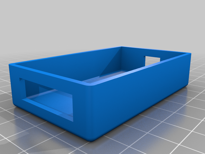
Housing for 5A CC-CV Module (LED Drive / Lithium Charger etc..)
There are a lot of these about (I use quite a few), so I decided to build an enclosure for them.
Usage:
+ Charge Batteries...
+ Drive LED Strips...
+ Build a rudimentary power supply with current limiting...
Options: Replace the existing presets with ten-turn pots for greater precision...
The device displays information rotating through, Voltage In, Voltage Out, Current drawn by the load, and Power used.
Pressing the right buttons rotate through the display options (latching the data), press again to advance to the next display option. The last press restarts rotating sequence displaying each value for a second or two...
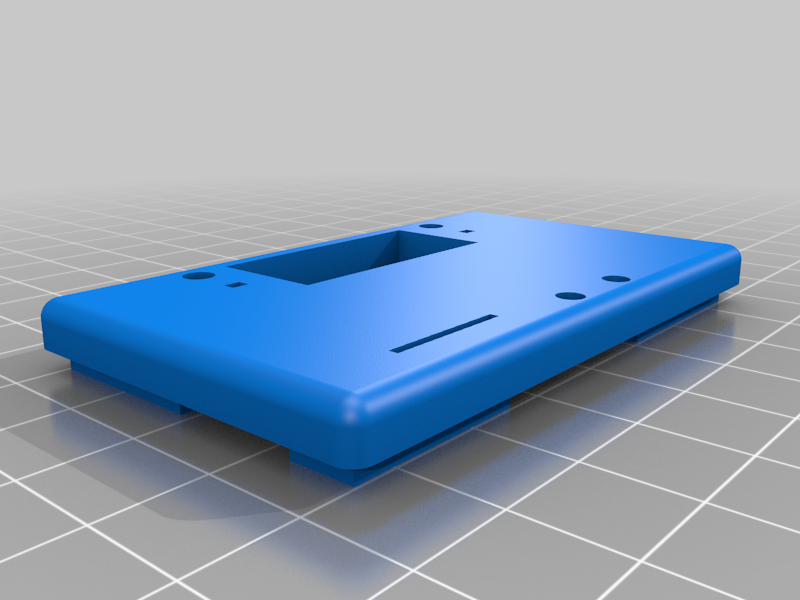
I've included some cut-outs to allow adjusting the unit while boxed.
The Final Version Filename is: HFB5Av3F
The Module:
- Input voltage range:5-36VDC
- Output voltage range:1.25-32VDC adjustable
- Output current: 0-5A
- Output power: 75W
- High efficiency up to 96%
- Built in thermal shutdown function
- Built in current limit function
- Built in output short protection function
- No input reverse polarity protection (if required, high current diode in series with the input).
These are not indestructible, I've killed one but I don't know why. A fan may be required for high current use. Otherwise all the remaining boards are working well for over two years, I originally purchased 8 units @ half the current price...
======================================================================
I found the following information for the module (posted here just in case)
Use as a step-down modules with over current protection:
+ Adjust the right button so that “OUT” LED lighted (digital meter shows the value of output voltage)..
Adjust the “voltage potentiometer” so that the output voltage reaches the value you want.
Adjust the right button so that Digital meter shows the value of output current; Wire shorted output terminal, then adjust the “current potentiometer” so that the output current reaches a predetermined over current protection value. (For example, the Digital meter displays the current value of 4A, then you can use the module to a maximum current of 4A)
Connected to the load.
Use as a battery charger
+ 1 Make sure you need to charge the battery float voltage and charging current;
Example: if lithium parameters 3.7V/2200mAh, then the float voltage is 4.2V, the maximum charging current 1C, ie 2200mA...
2 Under no-load conditions, adjust the “Voltage potentiometer” so that the output voltage reaches the float voltage;
Example: if to 3.7V rechargeable lithium battery, the output voltage can be adjusted to 4.2V...
3 Adjust the right button so that Digital meter shows the value of output current;
Wire shorted output terminal, then adjust the “current potentiometer” so that the output current reaches a predetermined Charging current value.
4 Charge turn lamp current factory default is 0.1 times the charging current;
Battery during charging current is gradually reduced, if the charge current setting is 1A, then when the charge current is less than 0.1A, blue lights turned off, the green light is on, which means that the battery is fully charged...
connected to the battery charge.
(1,2,3,4 steps as: Output is unloaded, do not connect the battery)
Use as a LED constant current driver module
+ 1 Adjust the “voltage potentiometer” so that the output voltage reaches the value you want.
- 2 Adjust the right button so that Digital meter shows the value of output current;
Wire shorted output terminal, then adjust the “current potentiometer” so that the output current reaches a predetermined LED operating current.
- Connect LED.
(1,2 steps as: Output is unloaded, do not connect LED)
Voltmeter and ammeter calibration method:
Module with manual calibration function can correct display precision voltage and current, if you think the current voltage and current accuracy to meet the requirements, do not perform the following operations.
(1) Output voltage calibration steps
Step 1:
Adjust the right button so that “OUT” LED lighted, Digital meter shows the value of output voltage;
Press the right button for more than 2 seconds, release, Digital meter and “OUT” LED flashes in synchronization so that you enter the output voltage calibration mode.
Step 2:
Press the right button (normal speed), the voltage value is adding up a unit; Press the left button, minus a unit; Due to a unit is less than 0.1V, the minimum voltage display to 0.1V, so you need to continuously press 1-5 times to see the voltmeter change 0.1V, how many times voltmeter change 0.1V by pressing the key, depending on the current display voltage, the higher the voltage, the fewer the number of press.
Step 3, press the right button for more than 2 seconds, release, to exit the output voltage calibration mode. All parameters set to automatically power down to save.
(2) Input voltage calibration steps
Step 1:
Adjust the right button so that “IN” LED lighted, Digital meter shows the value of input voltage;
Press the right button for more than 2 seconds, release, Digital meter and “IN” LED flashes in synchronization so that you enter the input voltage calibration mode.
Steps 2 & 3:
See output voltage calibration method.
:format(webp)/https://fbi.cults3d.com/uploaders/28098010/illustration-file/7f4f67db-9ca4-450e-85f1-24e0244ba98a/416178dc-cc8c-4305-8aae-2e9d34f1dbb4.png)


/https://preview3d-images.cults3d.com/mlssrov1hlgx8innw19uslmgz5an)
/https://preview3d-images.cults3d.com/r4i2y9a669zm8b8k573064pn3u42)
/https://preview3d-images.cults3d.com/ypr2xpqcbge3z2e5m2c156qacc0q)
/https://preview3d-images.cults3d.com/mul9ad237ivqbh1rq4bohxrm9zs8)


