For details on modifying the OpenSCAD file, scroll down. Otherwise, keep reading.
The STLs are named with the motor shaft size, and the o-ring cross-section diameter (CS) and internal diameter (ID). For example, "BiohazardWheel-4mm-7CS-95ID" is rendered for a 4mm motor shaft, with an o-ring that has a cross section diameter of 7mm and an internal diameter of 95mm. Fractional numbers are probably metric equivalents of SAE units. (See below for details.) In some cases, I've set the "stretch" parameter, which stretches the tire out a bit for a tight fit.
Here's how to use these wheels:
1) Print the part.
2) Drill out the motor shaft hole and the set screw hole for a perfect fit.
3) Push an M3 nut into the captive nut trap with a soldering iron. (If you don't want to do this, you can change the nut diameter and thickness in the OpenSCAD file for an easier fit.)
4) Put the tire on the wheel, and the wheel on the robot.
5) Watch carefully and see if your robot is cool enough to adapt to having only one wheel.
Do you know of any common and inexpensive o-ring sizes? If so, please let me know so I can create STLs for them! Here's what I have so far:
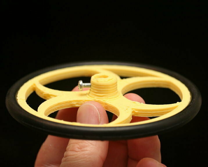
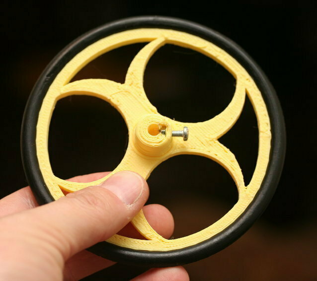
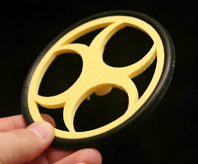
BiohazardWheel-4mm-7CS-95ID: 4mm, 7mm, 95mm. This is the size I happened to have on hand. This is the one shown in the photos.
BiohazardWheel-4mm-4.76CS-149.23ID: 4mm, 5-7/8", 3/16". This seems to be a popular size on ebay.
BiohazardWheel-4mm-2.38CS-55.56ID: 4mm, 2 3/16", 3/32". This is another size I found on ebay. I set this one to chamfer the top and leave the bottom of the hub alone.
Modifying the OpenSCAD File
There are a number of parameters you can use to get just the size you need. The OpenSCAD file will also echo out some helpful calculations for you.
O-Ring Tire Parameters: Often wheels are built around the tires. In this section, specify the properties of te o-rings you're using as tires.
tireCSDiameter - ring cross-sectional diameter (CS) -- How thick is the o-ring rubber?
tireID - O-ring Internal diameter (ID) -- How wide is the inside opening?
tireStretch - O-ring circumferential stretch percentage (usually 0-5%) -- How much to you want to stretch it to get it on?
Other general wheel properties: These properties define other general wheel metrics. Because I wrote this to build a number of different wheel types, you'll see properties like "numberOfSpokes." You can change the code in spoke() to create any spoke design you want.
wheelWidth - The width (or thickness) of the the wheel.
rimHeight - The height of the rim portion of the wheel. (Must be greater than tire CS radius.)
numberOfSpokes - Number of "spokes." Leave this at three if you're doing the biohazard design
Hub properties: These properties define the hub -- or how the wheel connects to the motor. The default values for the captive nut are precise for a M3 nut and will make the nut a very tight (if not impossible) fit. I prefer this because it allows you to "melt" the nut into place with a soldering iron. However, if you don't have a solder iron or prefer a looser fit, then just adjust the nut diameter and thickness. Similarly, the holes for the motor shaft and grub screw are also precise. This allows the holes to be drilled out for a more precise fit. Again, you can adjust these to suit your needs.
The hubZOffset can be used to "sink" the hub into the wheel, and it defaults to half the wheel thickness. For example, when the hubHeight is 10 and the hubZOffset is -2, then the hub will protrude 8mm from the wheel, but the shaft hole will be 10mm deep. The set screw will still be positioned in the middle of the exposed vertical height, and the fillet/chamfer will also be rendered in the correct position. This property is also useful if you want to poke a hole entirely through the wheel. (e.g. If the wheel is 6mm thick, set the hub height to 16 and the hubZOffset to -6, and you'll get a hub that protrudes 10mm from the wheel surface with a hole that extends all the way through the wheel.)
hubDiameter - The diameter of the hub portion of the wheel
hubHeight - The height of the hub
shaftDiameter - The diameter of the motor shaft
setScrewDiameter - The diameter of the set screw. 3 is the default for an M3 screw.
setScrewNutDiameter - The "diameter" of the captive nut, from flat to flat (the "in-diameter")
setScrewNutThickness - The thickness of the captive nut
setScrewCount - The number of set screws/nuts to render, spaced evenly around the shaft
hubZOffset - The Z position of the hub, negative numbers from the surface of the wheel
baseFilletRadius - The radius of the fillet (rounded part) between the hub and wheel.
topFilletRadius - The radius of the fillet (rounded part) at the top of the hub.
chamferOnly - Set to true to use chamfers (straight 45-degree angles) instead of fillets.
:format(webp)/https://fbi.cults3d.com/uploaders/31033408/illustration-file/c285354c-a662-4bec-a015-463b2bc33e5f/wheel-01_display_large.jpg)
/https://preview3d-images.cults3d.com/dpvc4fhfqqcrtfx65k07tis7n1un)
/https://preview3d-images.cults3d.com/4bbb1zps3lyjeslnklptvkghnemo)
/https://preview3d-images.cults3d.com/z0q16m83c5dhggvaxitta8r04u9h)


