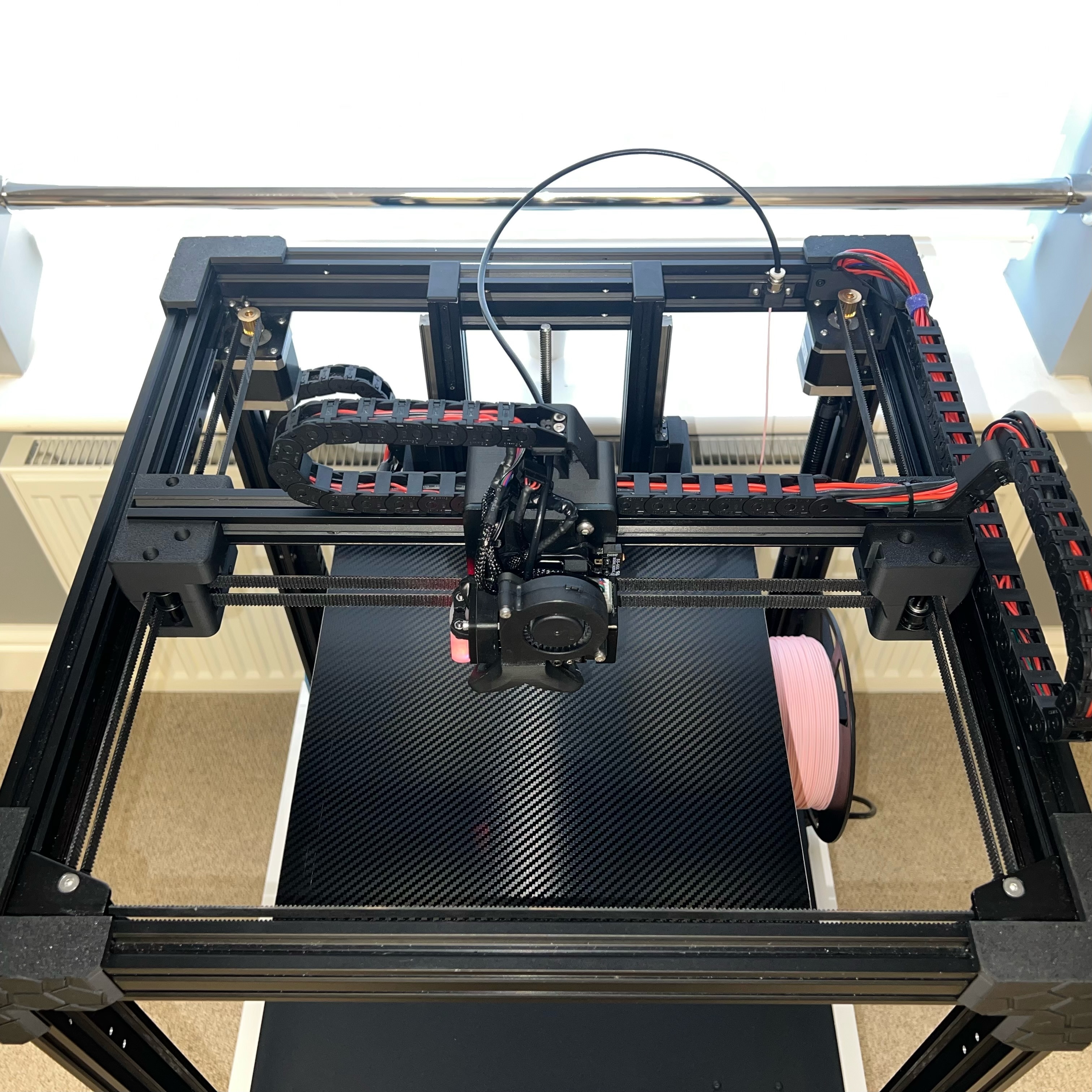
I have designed these mounts to work with the original Ender 6 motion system components. Again, these mounts allow you to upgrade from v-slot wheels to high precision, low maintenance linear rails.
To install this upgrade, you will need the following hardware:
Y-Axis Only
2 x 350mm MGN12H Linear Rails
4 x M3 4mm Button Head Screws to secure the mount to the linear rail carriages (2 per carriage)
2 x M3 8mm Cap Head Screws to secure the mount to the linear rail carriages (1 per carriage)
2 x M3 30mm Cap Head Screws to secure the mount to the linear rail carriages (1 per carriage)
2 x M4 40mm Cap Head Screws for the Y-Axis rail mounts
2 x M4 nuts for the Y-Axis rail mounts
To install the Y-Axis linear rails, you will need to print a couple of 2040 MGN12H alignment blocks to help install the Y-Axis rails square to the frame
Optional X-Axis with cable chain
1 x 350mm MGN12H Linear Rail
4 x M5 nuts to help secure the Ender 6 hot end bracket to the X-Axis mount
4 x M3 8mm Cap Head Screws to secure the mount to the linear rail carriage
6 x M3 4mm Heat Set Inserts
1 meter of 10mm x 11mm Outside Open Cable Chain with the 3 hole connectors
8 x M3 4mm Countersunk Screws (for attaching the Cable Chain)
To install the X-Axis rail, you will need a couple of 2020 MGN12H alignment blocks to help install the X-Axis rail square to the extrusion.
You will also need at least 4 x M3 8mm Cap Head Screws and 4 x M3 T-Nuts per linear rail. This is a minimum, some people secure with every other hole on the rail, some people secure using every hole. The more the better really.
Printing
I print all of my mounts in ABS due to it being a strong filament that will last. If you plan on printing in an enclosure, I wouldn't recommend PLA due to the fact these mounts will be carrying the hot end and the heat could cause them to warp/sag over time.
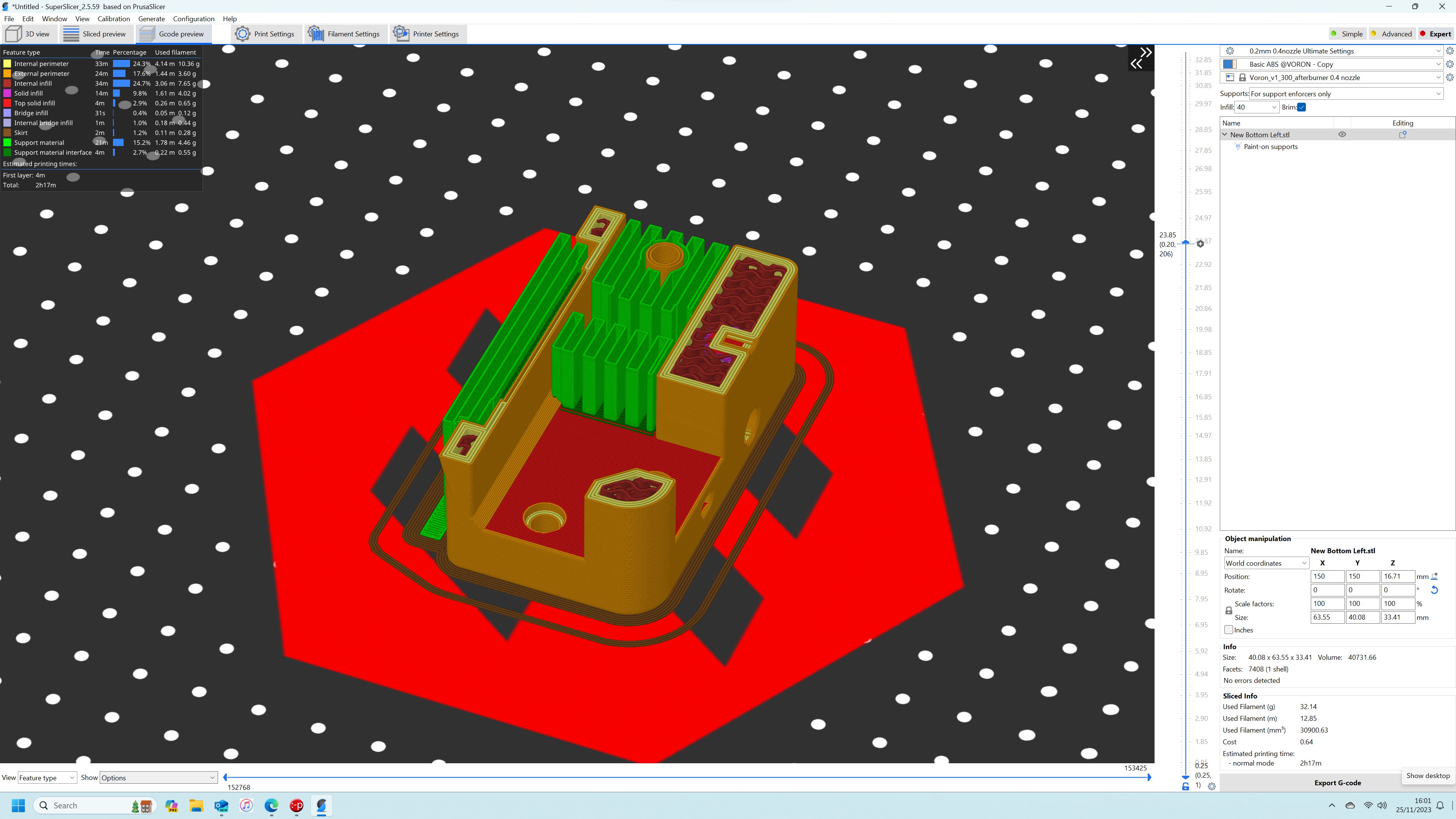
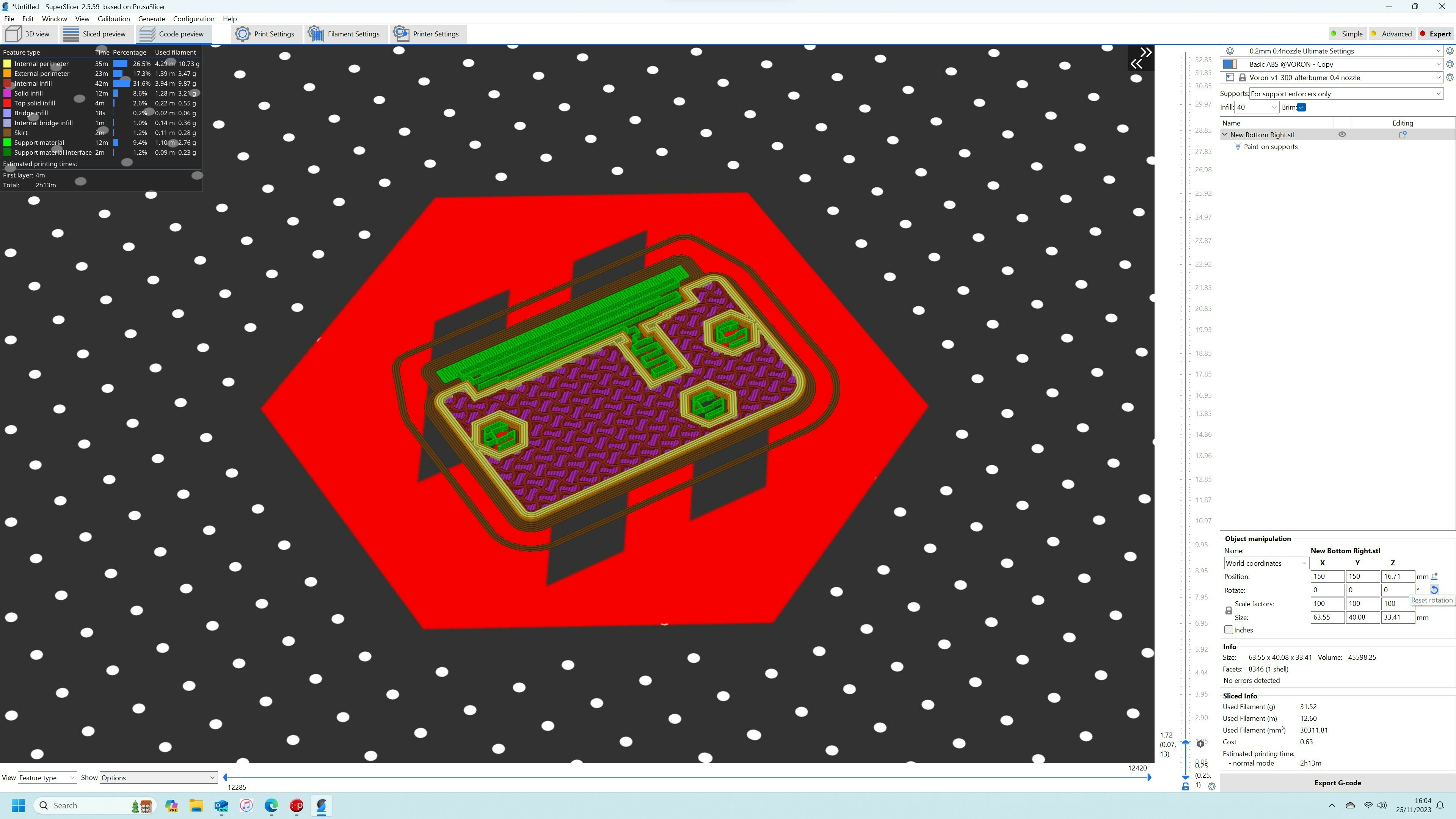
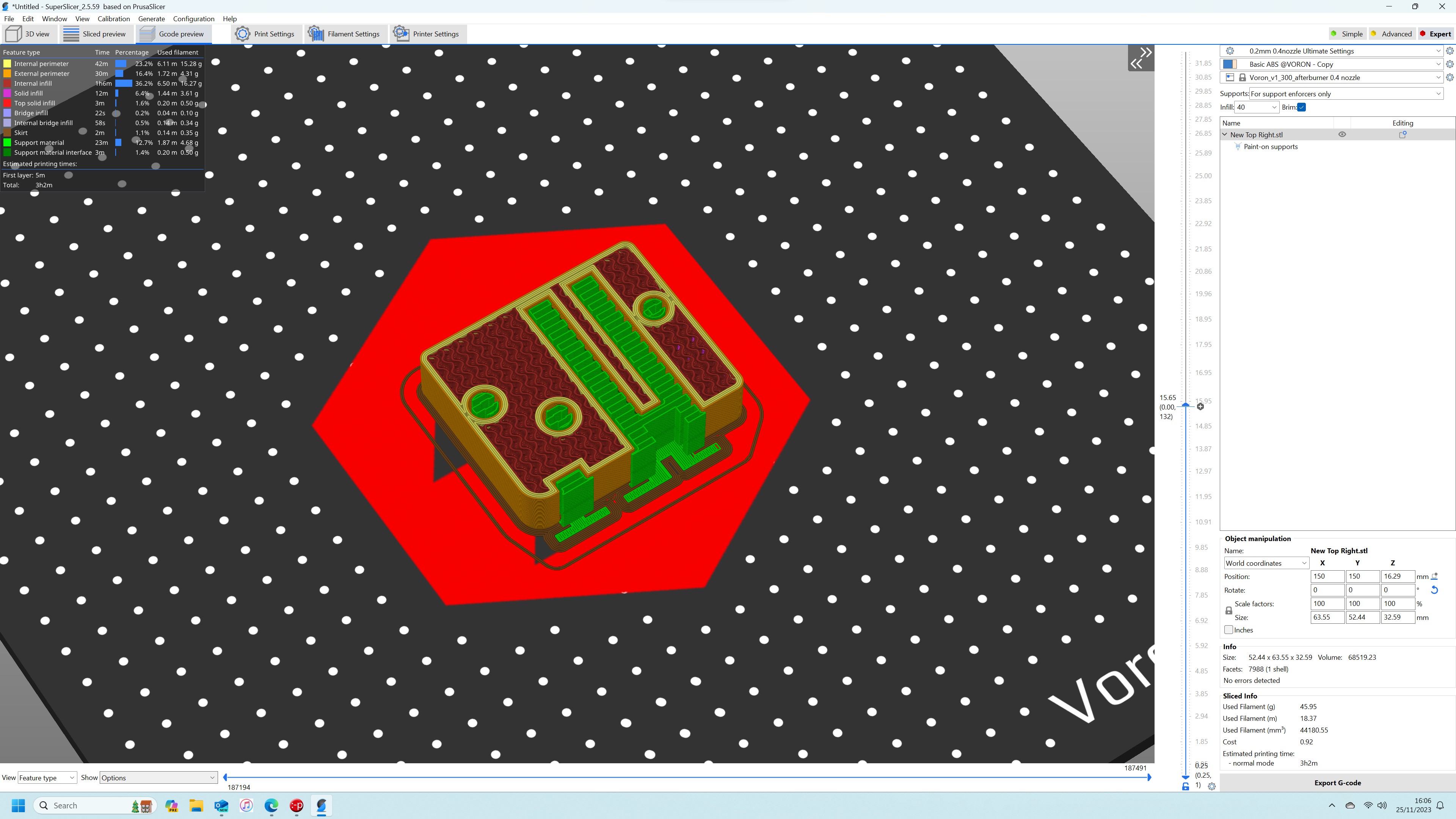
You will need to print one of each file using the settings listed below. Be sure to add supports like in the attached slicer images:
• Layer height: 0.2mm.
• Extrusion width: 0.4mm, forced.
• Infill percentage: Minimum 40% (or higher)
• Infill type: gyroid.
• Wall count: 4.
• Solid top/bottom layers: 5.
I use a 4mm brim when printing these parts to eliminate any chance of the corners rising during the print.
Installation
First install your two linear rails to the Y-Axis 2040 extrusions. The rails need to be fitted to the lower section of the extrusion. Remember to use your alignment blocks to ensure the rail is square to the extrusion.
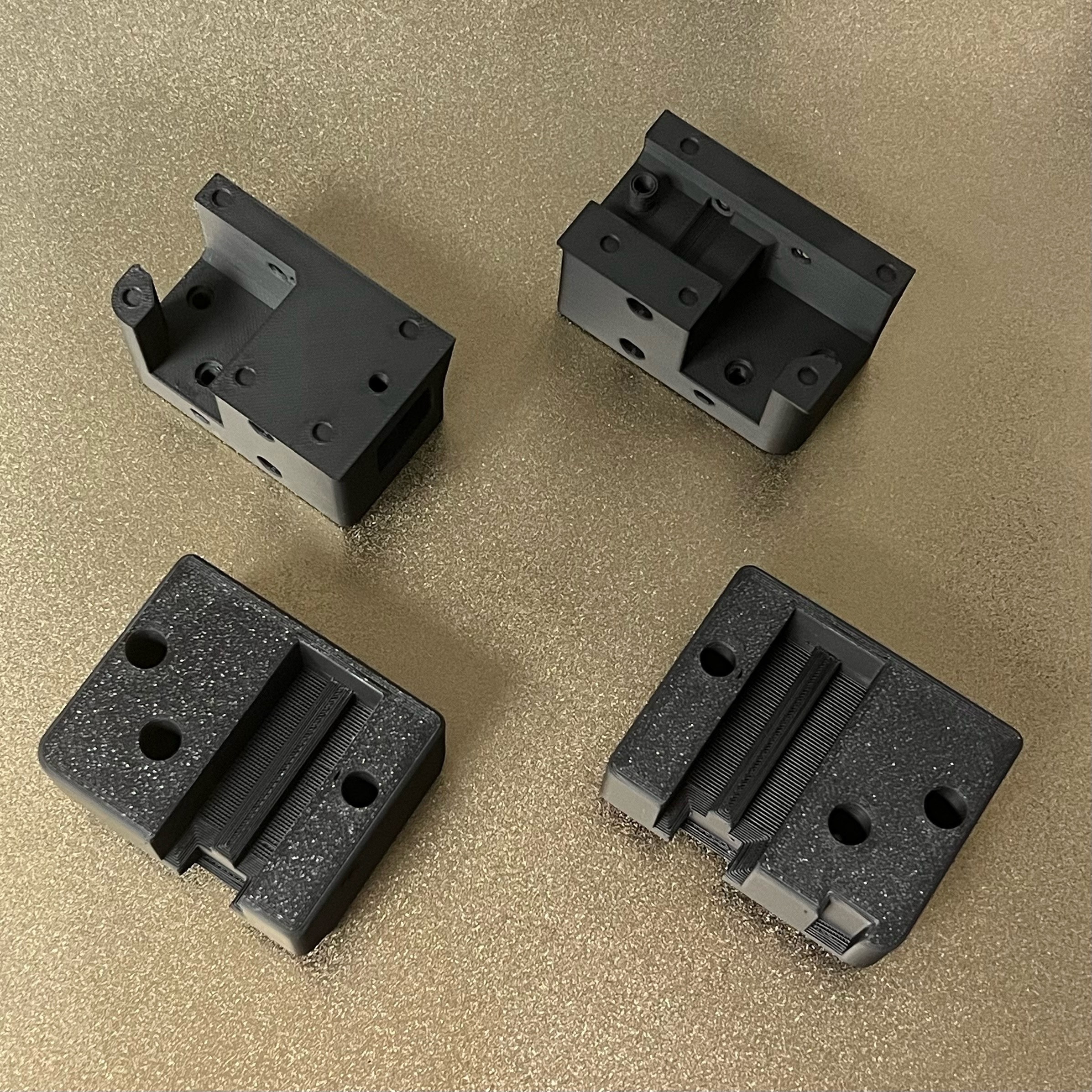
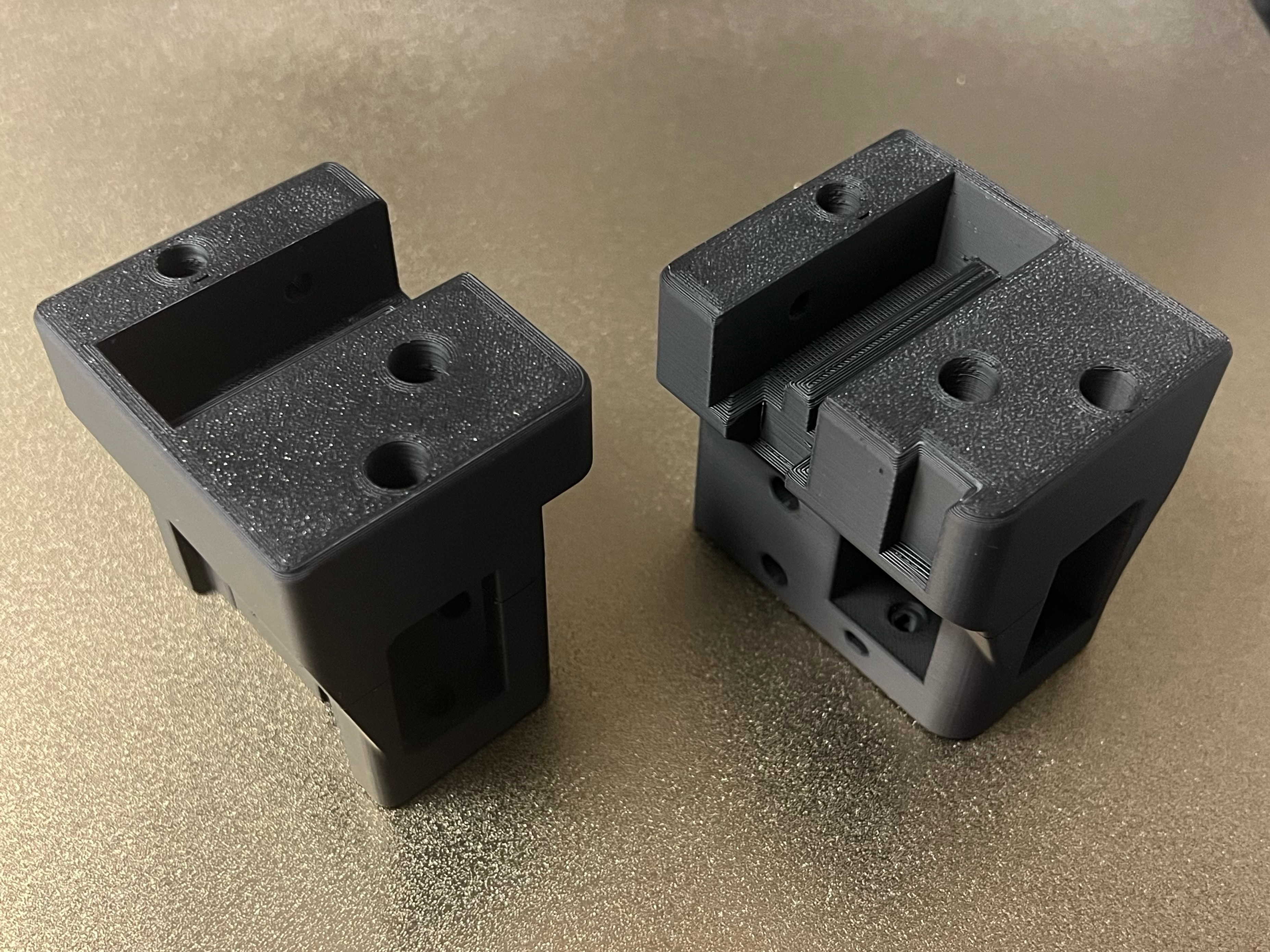
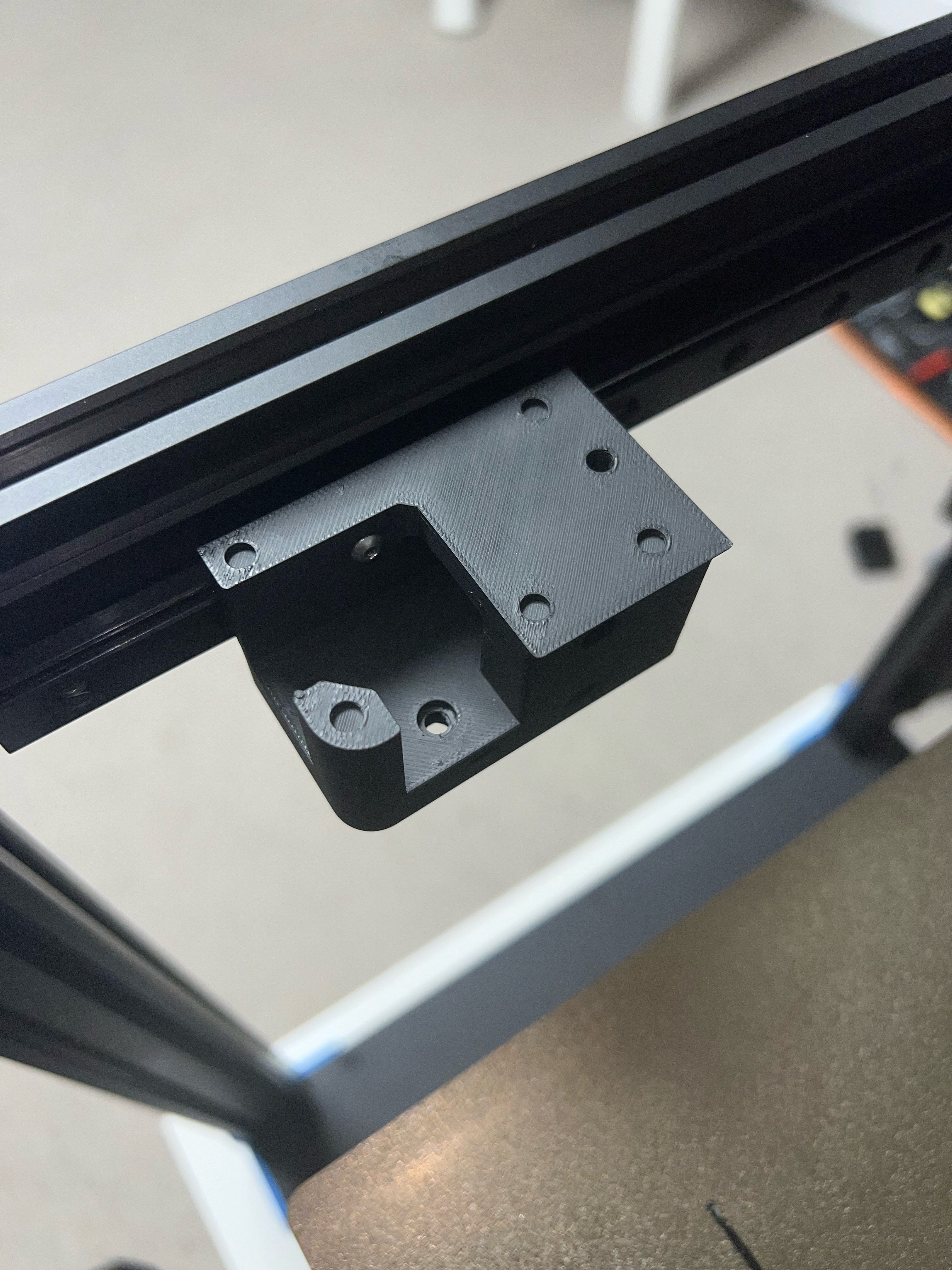
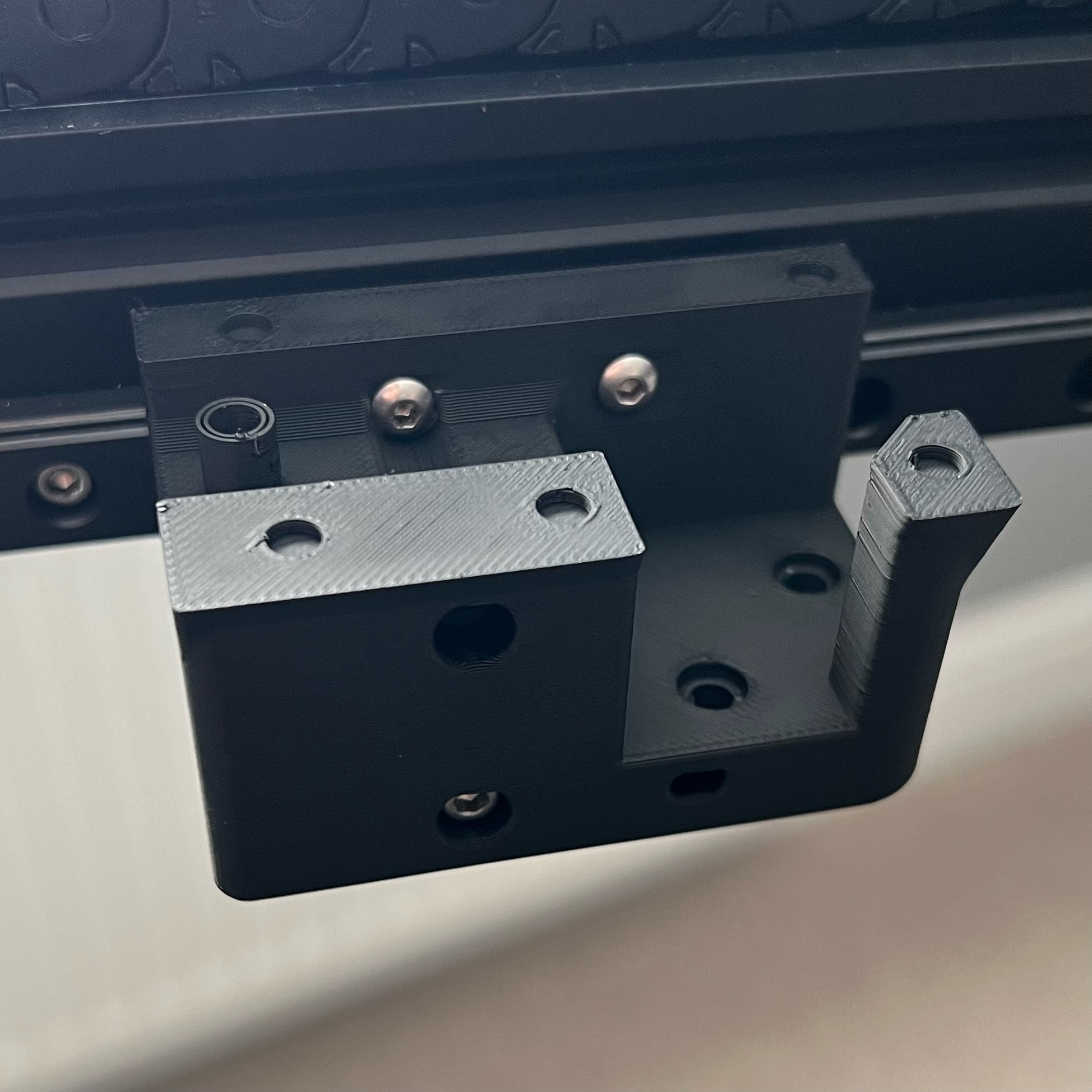
Take the left side bottom mount and secure it to the linear rail carriage block. The two M3 4mm Button Head Screws go in the top holes (do not over tighten these as the walls are very thin on this section of the mount) . Put the M3 30mm Cap Head Screw in the bottom right hole and finally the M3 8mm Cap Head Screw in the bottom left hole.
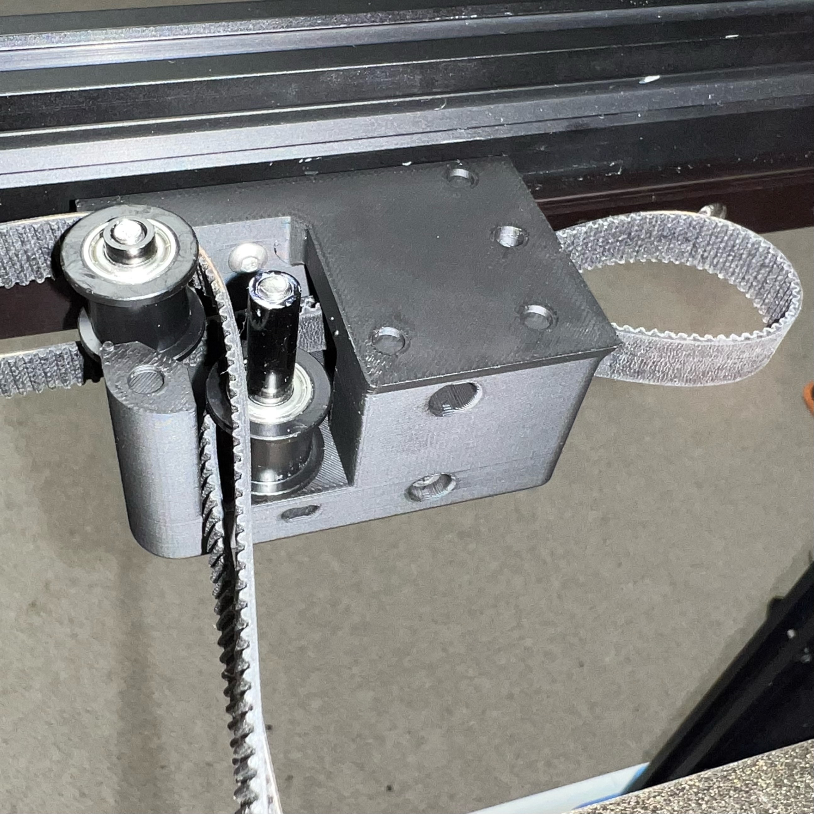
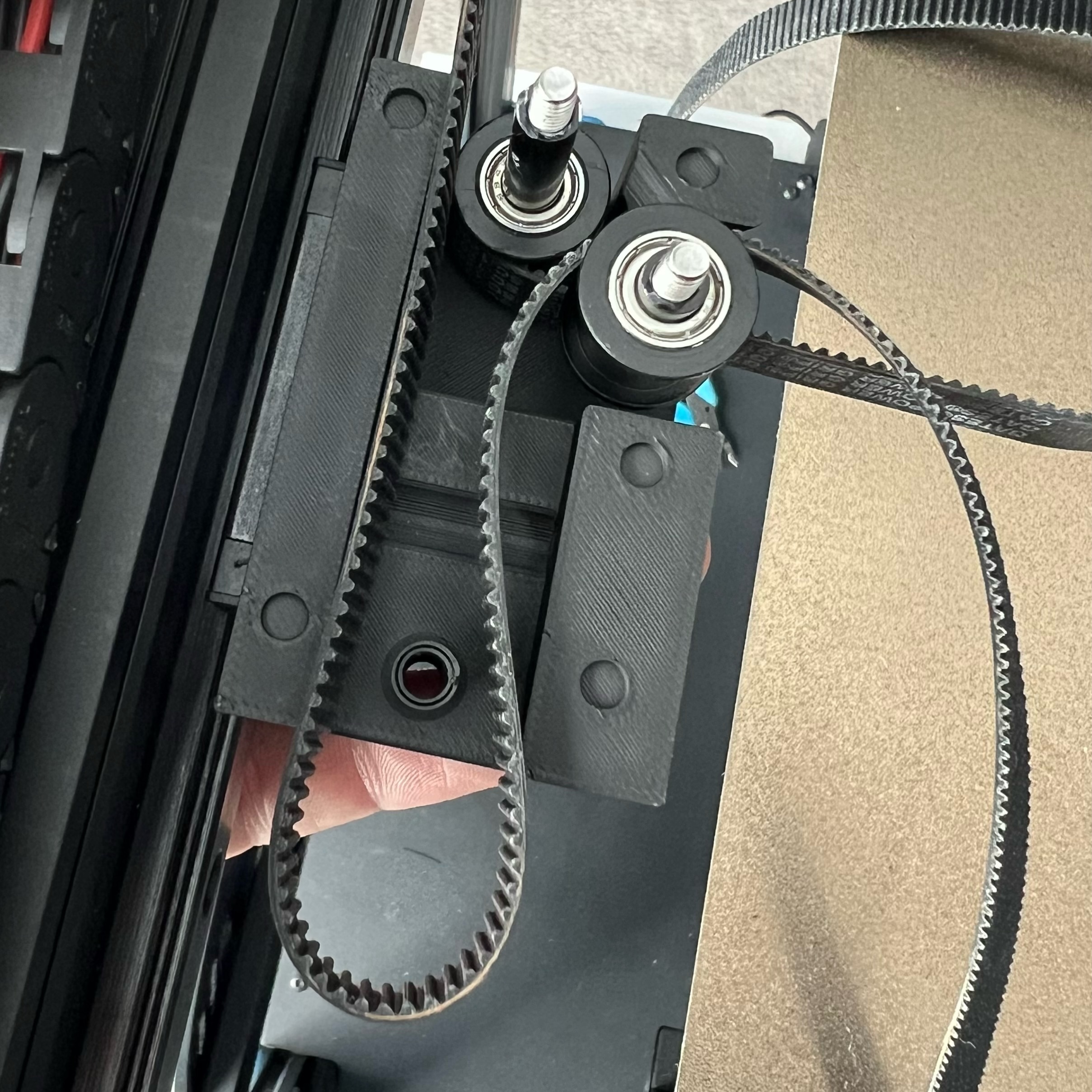
Now you need to stack the big spacer/pulley/small spacer in the front hole. I use an Allen Key through to temporarily hold them in place. Then stack the small spacer/pulley/big spacer in the right hole and use another Allen Key through the hole to hold them in place. Now feed your bottom belt straight through the mount towards the motor and return it back through and around the bottom pulley and to the centre of the printer. Then feed the top belt around the front pulley and to the centre of the printer.
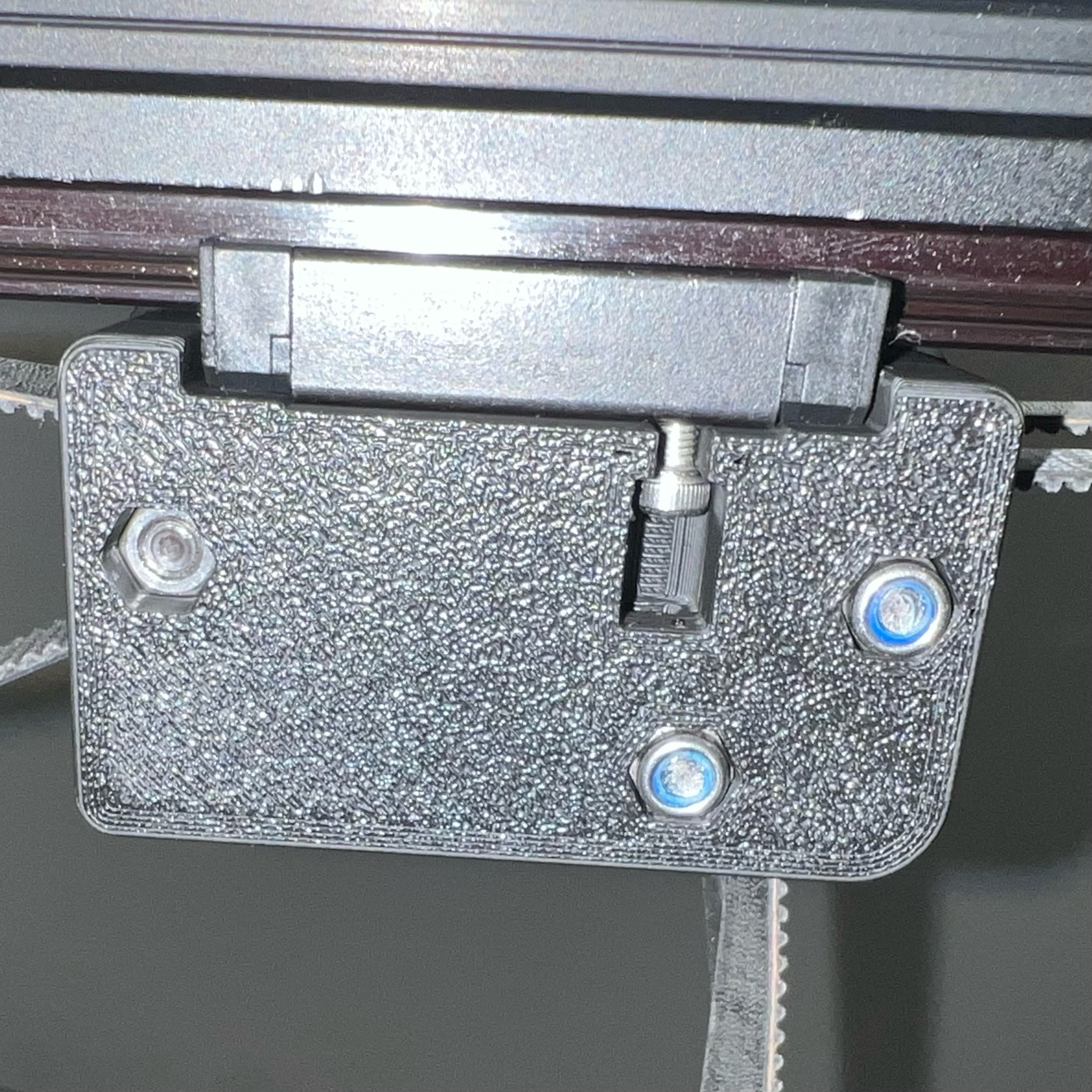
Once you are happy with your belt paths, fit the top part of the mount on to the bottom and insert the two Ender 6 counter sunk screws through the spacer/pulley holes from the top. Then lock them in place by putting the Ender 6 Nyloc nuts in the underside of the bottom mount and tightening the two screws. Then insert the M4 40mm Cap Head Screw through the rear hole of the top mount and secure with the M4 nut on the underside.
Repeat this process for the right side and remember that for this side the front pulley is at the bottom and the left pulley is at the top.
If you are not using the supplied X-Axis Cable Chain carriage mount then you can now fit your X-Axis extrusion into the mounts and secure them in place using an M3 T-Nut and M3 8mm Cap Head Screw (one of each per side). There is a hole in the back side of the top mount for this purpose.
You can now refit your belts and get printing.
To use the Cable Chain option you will have to rewire the printer from the hot end to at least the breakout board. A lot of people bypass the breakout board as it is known to cause issues, especially with BLTouch/CR-Touch. I have rewired straight down to the main board using 24 gauge Ultra Flexible Silicone wire
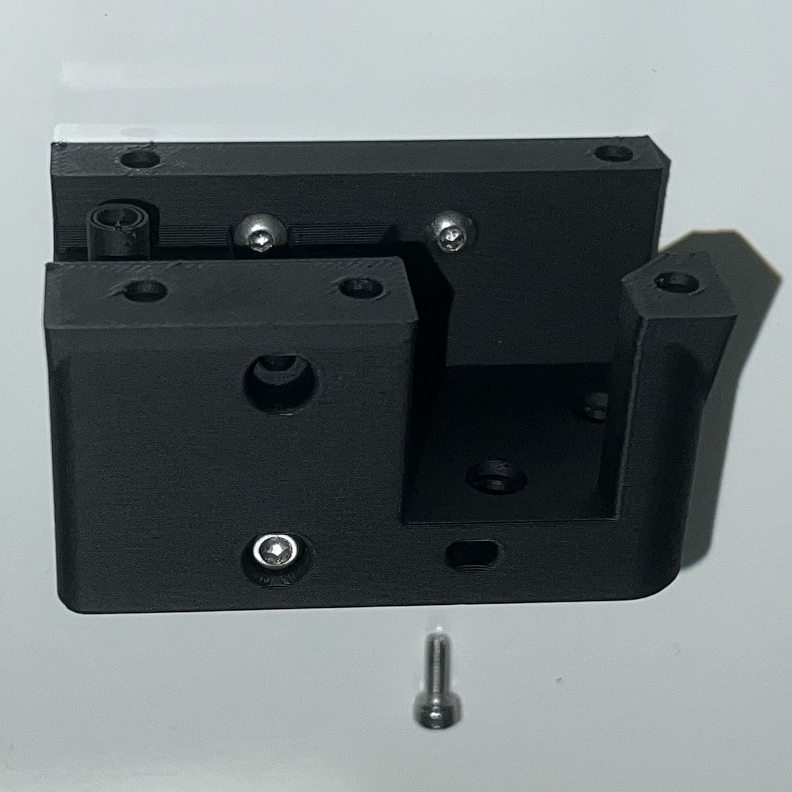
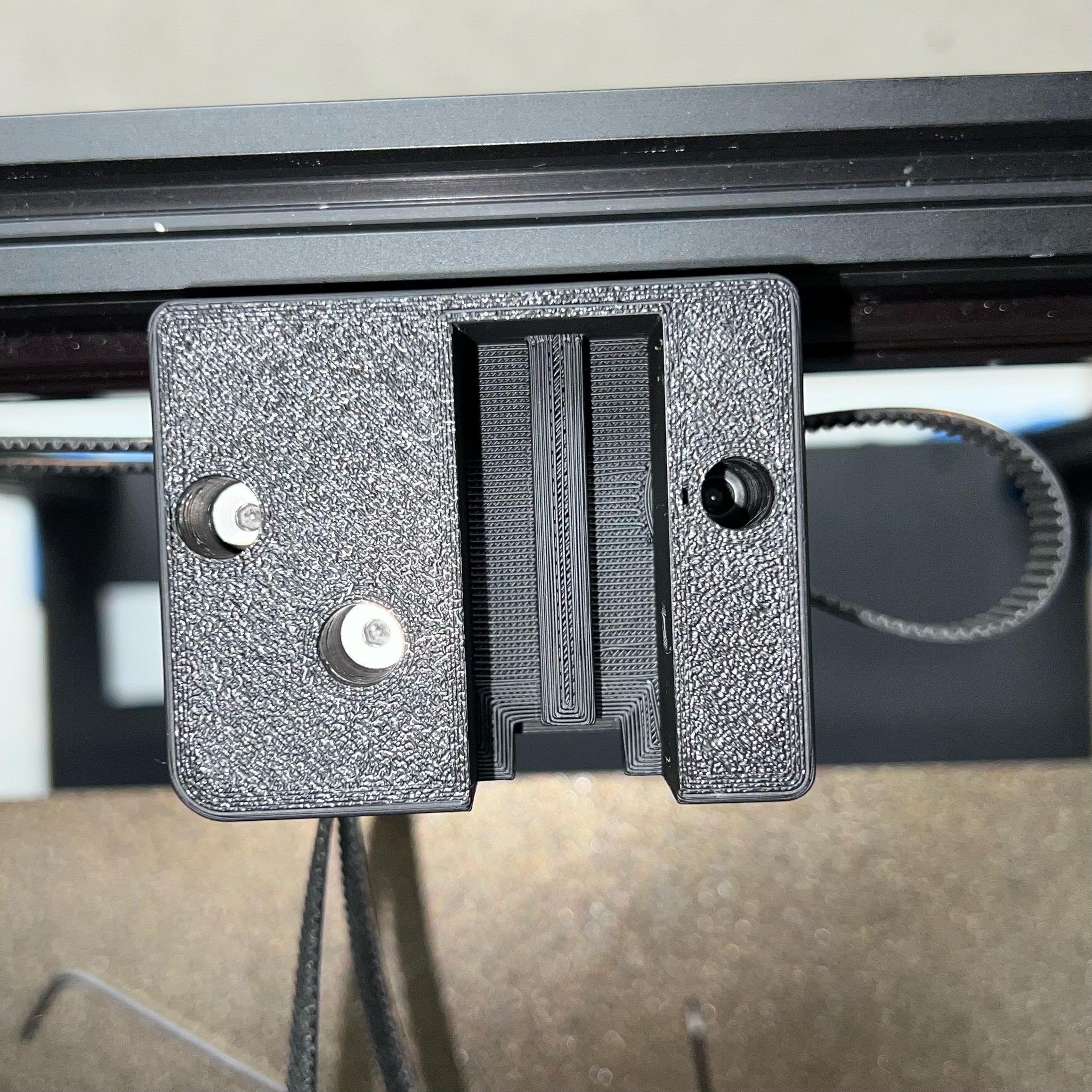
If you are using the supplied X-Axis Cable Chain mount then you will first need to install your linear rail to the underside of the X-Axis extrusion, remembering to use your alignment blocks to ensure the rail is square to the extrusion.
Now insert two M5 nuts into the bottom holes in the carriage mount and then slide the mount over the linear rail carriage block. Secure the mount to the linear rail carriage block with 4 M3 8mm Cap Head Screws. Now insert two M5 nuts into the top holes on the mount and attach the Ender 6 hot end plate to the mount using the four original Ender 6 M5 10mm Button Head Screws.
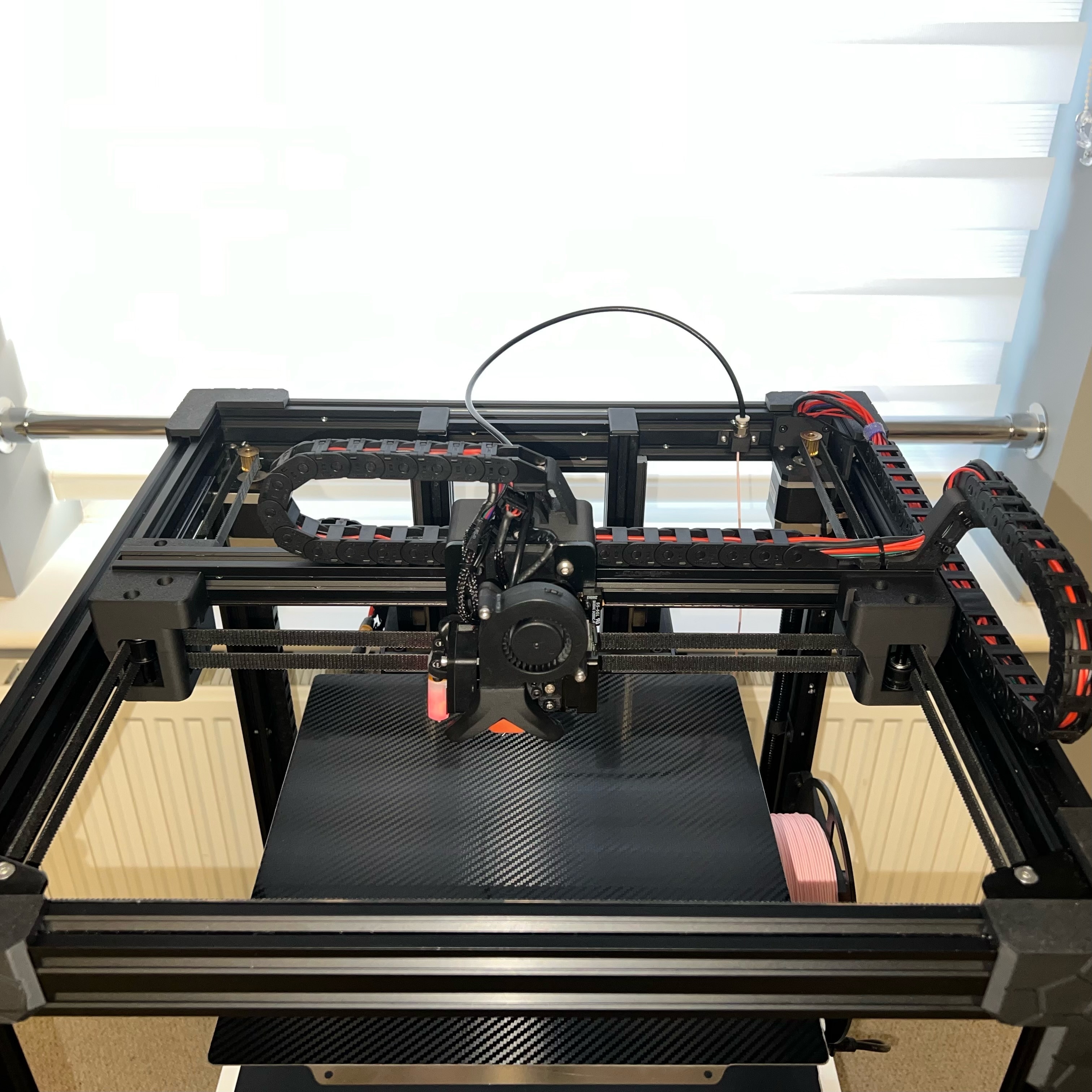
You can now fit your X-Axis extrusion into the Y-Axis mounts and secure them in place using an M3 T-Nut and M3 8mm Cap Head Screw (one of each per side). There is a hole in the back side of the top mount for this purpose. You can now refit your belts.
Now its time to fit your heat set inserts, three on the X-Axis carriage top mount and three on the XY Joint Cable Bridge. Attach the XY Joint Cable Bridge to the X-Axis extrusion using an M3 T-Nut and a small M3 screw (you can use a Cap Head or Button Head Screw for this). Then measure out your cable chain and trial fit it to both the X and Y Axis. Once you are happy with the length you can remove it and start the process of feeding your wires through from the hot end down to the main board. If you get the Outside Open type cable chain, this is a lot easier to do as the chain clips open for you to insert the wires and then clips shut again.
Now attach both ends of the X-Axis Cable Chain. Use 3 x M3 4mm countersunk screws to attach it to the X-Axis carriage and 1 x M3 4mm countersunk screw and M3 T-Nut to attach it to the extrusion next to the XY Joint Cable Bridge. Then attach the other Cable Chain to the Y-Axis using 3 x M3 Countersunk Screws on the XY Joint Cable Bridge and 1 x M3 4mm countersunk screw and M3 T-Nut to the extrusion at the back right of the printer.
I routed my hot end wires down the back right extrusion using 18mm conduit similar to the one Creality used for their hot end wires. If you want to try this method, message me on here and I will send you the files for the conduit clips. With the breakout board removed the wires can run straight down and it gives a much cleaner look to the printer.
That's it, another one finished!!!
Time to go and print something : )
:format(webp)/https://fbi.cults3d.com/uploaders/21622598/illustration-file/89acc111-0582-4f19-a450-a2e74af1142f/1.jpeg)


/https://preview3d-images.cults3d.com/by2pysmoxcj72g8ou01g3suf5kb1)
/https://preview3d-images.cults3d.com/qo913j6zn0zyiomxqje7vy331avj)
/https://preview3d-images.cults3d.com/m9k981ecydjaulhspvpn9hn0iu7p)
/https://preview3d-images.cults3d.com/drku3yivczu09ab8p0xw9f6bguj6)
/https://preview3d-images.cults3d.com/1qwxmgfvboj291vjvjhvh0q1spi5)
/https://preview3d-images.cults3d.com/79xumtte1a2e0hr2wgeg1ag656x8)


