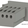
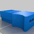
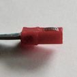
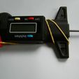
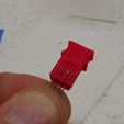
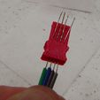
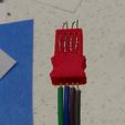
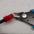
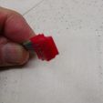
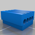
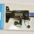
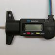
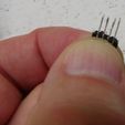
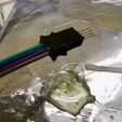
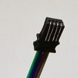
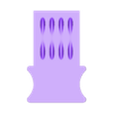
This is a data connector for some of the Chinese calipers and tire depth gauges. If the button layout is the same as shown in the pictures, this connector will probably work.
For step by step instructions for building this connector cable for the SMD caliper data interface board, visit: https://www.instructables.com/id/Caliper-Data-Interface/
Note that as of 03-APR-2019 there is a version 2 of this connector described at the end of this summary.
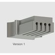
Version 1
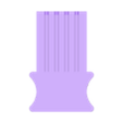
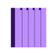
Print both STLs at 0.1mm layer height, 20% infill, no support, with just a skirt, no brim (if you print with a brim it’s a pain to cleanup)
For wire I used 26AWG 1.27mm pitch flat cable. This is the ubiquitous “jumper cable” product you get with Dupont connectors already attached.
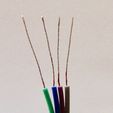
For this connector you need 4 conductors, any color. Strip 2cm of insulation off one end as shown in the pictures. Apply solder to the first 15mm of wire from the tip to stiffen the wire. After cleaning up the print of Connector.stl, use a 1.5mm drill bit to enlarge the exit holes and to remove any material in between. The goal is to be able to insert all 4 insulated conductors bonded together as shown in the picture. Using the ConnectorNoHandle print, place the 4 soldered conductors in the 1.5mm on center cuts and use this as a guide to insert the wires into the connector with a handle. After verifying that you’re able to insert the insulated cable into the exit holes approximately 5mm, withdraw the wire till the bare wires are exposed. Apply some plastic epoxy to the insulation and reinsert the wires. Put the assembly aside and wait for the epoxy to cure. Once cured fold the 4 wires around the end of the connector, cleaning up the soldered ends as needed.
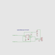
The data and clock signals coming from the caliper are 1.5v. I’ve included a simple circuit to level shift to 5V (VCC in the circuit). The only reason I used a comparator to do the level shifting is that that’s what I had on hand. Use whatever you have available to do the unidirectional level shifting. Note that you DO NOT want a bidirectional circuit.
I’ve also included a simple Arduino sketch so you can see the raw data coming from the caliper.
The pin assignments, as shown in the pictures:
Green - GND
Blue - DATA
Purple - CLOCK
Gray - +1.5V
I chose a tire gauge because it’s cheap (~US$4), and it meets the future use as a height data probe for a project I’m starting. If you attach a low force spring to keep the caliper probe extended, then attach the tire gauge to a servo, Vwa-lah, you have a really inexpensive data probe.
https://www.aliexpress.com/item/WSFS-Hot-Digital-depth-gauge-caliper-tread-depth-gauge-LCD-Tyre-tread-gauge/32775295632.html?spm=a2g0s.9042311.0.0.FIUyIk
Note that the price varies. When I bought mine it was offered for less than US$4. I bought a few more at another site for a little less. If the unit body looks like the gauge/caliper in the picture, it’s probably OK.
Update 11-AUG-2017: Modified ConnectorNoHandle.stl so that insulated wires can be epoxied the same as the connector with a handle.
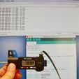
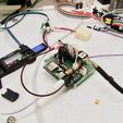
Update 22-AUG-2017: I uploaded a picture of my test setup. The caliper is being powered by a DC-DC regulator (shown in the beige box) to supply 1.5V. The data is being monitored by an ATTiny85, turning the caliper into an I2C device. Whenever the value changes, the ATTiny85 sets a signal wire high. The Arduino Pro mini, acting as the I2C master, then requests 3 bytes from the ATTiny85 via I2C. The ATTiny85 then resets the signal wire. If change notification isn’t needed, the master can, at any time, request the latest value from the ATTiny85 via I2C. If anyone is interested in the Arduino projects for what’s described in this update, let me know and I’ll upload them
Update 28-OCT-2017: See https://www.thingiverse.com/thing:2612218 for an implementation example that uses an I2C interface.
Update: 03-APR-2019
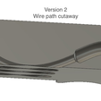
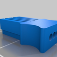
Version 2
I’ve added an updated connector. The improvements are:
- doesn’t have any sharp bends in the contact wires.
- forces the contact wires above the plane of the connector.
- contact ends are held in place
Downside:
- like the original connector, you still need to use a rubber band to keep the connector in place.
- cleanup is a bit more difficult than version 1.
Print at 100% fill, no support with just a skirt.
Because it’s such a tiny print I had to slow down the print and travel speed to 30mm/s, 60mm/s. (depending on the accuracy of your printer.)
The hole sizes are 1.4 and 0.8mm. I used a cheap set of PCB drill bits to clean out the holes.
( https://www.aliexpress.com/item/10PCS-package-tungsten-drill-bit-0-6-1-5mm-spiral-hand-drill-woodworking-tools-CNC-drill/32749247271.html )
Strip about 2.5cm of insulation and apply solder to stiffen the wire.
Use PCB cleaner to remove the flux residue.
Trim the soldered ends by removing the last 2mm.
Using the holes at the connector tip as a spacing guide, insert the connector wires and fish the wires through to the tip.
Push and pull the connector wires into the connector shell until the insulation is seated about 3 to 4mm into the shell.
Pull the insulated wires back until you see the bare wires.
Apply plastic epoxy
Push and pull the insulated wires into the housing.
Set aside and wait for the epoxy to cure.
Once cured, trim the ends of the connector wires flush with the connector tip.

/https://fbi.cults3d.com/uploaders/31968667/illustration-file/195e3816-a235-494d-90f8-66a5af8e395b/V2_Screen_Shot.png)
