Small version of Robothut's Rocking body drone
Small version of Robothut's Rocking body drone


Print Profile(0)
Description
Summary
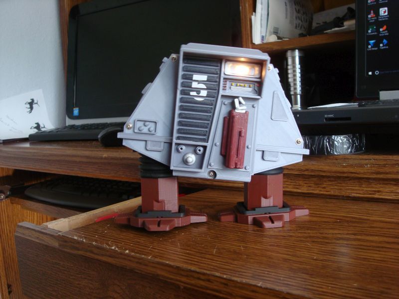
This is kind of a remix of Robothuts Rocking Body Walking Robot Drone #5. It's a much smaller version driven by an n20 gear motor. The toy is approximately 75 MM tall X 90 MM wide or 3 X 3.5 X 1.75 inches. The power source is 2 CR2032 cells wired in series. I used this combo on another walking robot I designed. It was designed from scratch in Fusion 360. It includes a built in battery box for the coin cells.
youtube video:
https://youtu.be/hNSt9VCsHqQ
The parts you'll need other than the 3d printed ones are:
M2 X 8 self tapping screws - 6 pcs for mounting leg-pins to cranks and front plate
M3 X 8 self tapping screws - 2 pcs for motor clamp
M3 washers - 6 pcs
22 gauge solid hook up wire for the battery contacts
small flexible stranded wire
3.125 MM X 42 MM brass rod
3.125 MM X 14.5 MM brass rod
switch from either a tea light or dual CR2032 battery box
I used 1/8 inch or 3.125 MM brass rod for the shafts but 3MM would probably work. The switch I used came from a CR2032 battery box but I found a similar switch in a tea light. The switch sets in a pocket and is held in place by the front panel which is screwed on with M2 X 8 screws.The back panel is glued to the main body. You can use the back pin to help align it. The contacts for the coin cell holders are made from solid 22 gauge hook up wire. I've included a jig for forming the shorter wires. The 2 short inner contacts are held in place by the motor clamp screws and washers. They need to be trimmed flush where they extend out the bottom. The single outer contact wire is threaded through the holes in the bottom and bent over the notches at the top of each cell holder.
When building the gear train, it's important that everything moves freely. This motor battery combination doesn't have a lot of power to overcome misalignment or tight spots. The 3MM washers on the main shaft act as spacers and bearings. The motor is held down by the clamp and can be adjusted up and down. This affects how freely the gears run. There is a 3 MM washer between the motor and its bevel gear. It acts as kind of a bearing. The top gear/cam combo has a 3.125 X 14.5 MM brass shaft pressed into it. Make sure this isn't longer since you have to flex the frame to insert this part. If it's longer you'll probably break the frame bending it.
The cranks that go on the end of the main shaft and the bevel gears with round holes are a little undersized for the 1/8 inch shaft. I drill them out with an 1/8 inch drill, making sure to dril the hole straight and with a low RPM. I made them small in case someone wants to use 3MM shafting. With 3d printing, small accurate holes are always a problem. The cranks go on with the holes 180 degrees from each other. The leg-pins are made in 2 pieces with a half lap joint to join them. They are glued together. I sand them flat after gluing to make sure the joint is flat. The legs are glued to the frame. The top gear/cam is timed to the main shaft so that when a pin is all the way down the body is pushed to the opposite side.
The toy can be printed and built in a day. You just have to check that the parts move freely at each step of the build. Some soldering is required to hook the motor to the switch and batteries. A partial front plate is included so you can see the internals working.
Good luck,
Rick
Print Settings
Printer:
Folger Tech
Rafts:
No
Supports:
No
Resolution:
.2
Infill:
20%