Skip to content

Sequential 4 Lock Surprise Gift Box Puzzle

Advertising
Advertising
?
Creation quality: 0.0/5 (0 votes)
Evaluation of members on the printability, utility, level of detail, etc.

  • 195 views
  • 2 likes
  • 1 download

License
3D design format
STL Folder details Close
  • Seq4LPB V2a - Bow.stl
  • Seq4LPB V2a - Box bot.stl
  • Seq4LPB V2a - Crank wheel1.stl
  • Seq4LPB V2a - Door.stl
  • Seq4LPB V2a - Drive pin.stl
  • Seq4LPB V2a - Key.stl
  • Seq4LPB V2a - Lock disk.stl
  • Seq4LPB V2a - Lock maze bot.stl
  • Seq4LPB V2a - Lock maze top.stl
  • Seq4LPB V2a - Lock pin1.stl
  • Seq4LPB V2a - Side strapB1.stl
  • Seq4LPB V2a - Side strapT1.stl

Learn more about the formats

Publication date 2024-03-09 at 11:43
Design number 1842503

3D printer file info

3D model description

Development
This was developed from my earlier puzzle box:
https://cults3d.com/en/3d-model/game/sequential-4-lock-surprise-puzzle-box

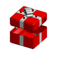
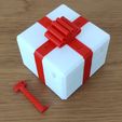
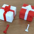
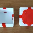
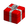
I realised that if I moved the straps a bit the box would become symmetrical and it could resemble a gift wrapped box. Little did I realise that every single part had to be redesigned.

All parts clip together, so no screws or glue is required for assembly.

With the initial design, I realised that the lock bar from my earlier puzzle was occupying a space in the box that reduced the volume available for objects. Now the lock bar has changed to a flat lock disk with detent springing provided by the decorative bow instead of a drive clip.

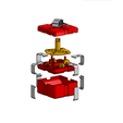
The mechanism
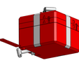
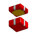
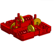
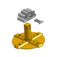
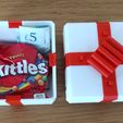
The box needs only one key to open it and this is neatly hidden in the lower compartment so that it remains with the puzzle. When you find the key, you have to work through each lock maze in turn to reach a crank wheel which can then be turned to lift or drop a locking pin. The internal locking bar can only be turned when all four locking pins have been lifted and then the decorative bow can be turned 45 degrees anti-clockwise to release the lower compartment. This should easily separate from the top lock section and can be used to hold a surprise like a small bag of sweets, chocolate treat or money.

Dimensions
Overall box: 72Wx72Dx54H
Lower compartment: 67Wx67Dx28H (approximate)

Assembly instructions
Follow the steps below:

  1. Prepare the lower box compartment by hooking the bottom side straps over the box top edge and pressing them firmly until they click into the recesses at the bottom of the compartment then check that the concealed door slides into place at the bottom.
    Note: if needed, these straps can be removed by pressing down the bottom clip from inside the box compartment.

  2. On the top and bottom halves of the lock maze, check that the lock pins move freely in the holes provided, filing or cutting the holes if necessary. Then push each lock pin through the bottom half of the lock maze so that they stick through and are supported by the side spring arms in the lower maze detents.

  3. Fit each crank wheel into position with the crank pin engaged into the lock pin at the lowest point.

  4. Make sure that the top and bottom lock maze symbols line up then lower the top half of the maze onto the bottom half while adjusting the lock pins from underneath to make sure that they align with the top.

  5. Fix the two maze halves together by hook four top side straps onto the top maze half and pressing down firmly at the side so that they click into the bottom maze half.
    Note: these straps can be removed using a screwdriver if the crank wheels and pins need to be accessed. This is acheived by removing the lock disk and then levering up the top edge near the drive hole, but it is best to ensure that the associated lock pin is in the down position first.

  6. Insert the drive shaft of the locking disk into the maze from the bottom and turn it to ensure that it aligns with detents on the maze bottom. Now fit the bow to the square drive on top and press down to align the bow pin slot with the drive shaft slot, then push the drive pin into the larger of the recesses on the side of the bow.
    Note: The bottom of the bow provides springing for the lock disk to move out of the detents on the maze bottom. If the lock disk is unwilling to move then you may have to file or cut down the 'pips' on the disk (perhaps cut away all but one or two).

  7. The complete maze assembly should now be in the lock position, so it's a good idea to test each lock with the key to make sure that no printing debris is blocking the maze. When the key is inserted fully into the maze, it should fit into the crank wheel so that the associated lock pin can be raised or lowered by turning the key. Leave each lock pin in the raised position so that the assembly can be locked/unlocked easily.
    Note: each crank wheel has a flat blade screwdriver slot at the bottom of the key hole so future assembly or lock/unlocking can be simply achieved with a screw driver (but don't tell your end users).

  8. When all the lock pins have been lifted, turn the central bow 45 degrees anti-clockwise to put the lock disk into the open position and then push the maze assembly onto the lower box compartment. Turn the central bow 45 degrees clock-wise so that the locking disk arms slide under the angled side straps on each wall of the lower box compartment.

  9. Each lock must now be solved again (or use a flat blade screwdriver) to reset all four locking pins into the down position.

  10. Finally, the key can be stored in the concealed compartment in the base of the lower box.
    Note: the compartment door has a flat feature at one end and this should be pushed in first with the flat part facing down. This leaves a gap at one end which allows a finger nail to hook the door open.

3D printing settings

Printing
This puzzle box has been printed in PLA.

You need to print 4 off Crank wheels, Lock pins, Top side straps and Bottom side straps.

The crank wheels are best printed with support to properly form the screwdriver slot.

The side straps must be printed on edge to achieve bending strength.

The Bow should be printed on it's side with the smaller clip opening towards the bed.

The key should be printed with the handle parallel to the bed and with support to achieve adequate strength. After printing, make sure the key fits easily into the keyhole and crank wheels, filing or cutting left over support material if necessary.

Cura Settings
Material: eSun PLA
Quality: 0.2mm
Wall thickness: 0.4mm
Wall line count: 2 (minimum)
Infill: 15%
Pattern: ZigZag
Support: Everywhere (but very small amounts used)
Build plate adhesion: None

Advertising


Issue with this design? Report a problem.

Would you like to support Cults?

You like Cults and you want to help us continue the adventure independently? Please note that we are a small team of 3 people, therefore it is very simple to support us to maintain the activity and create future developments. Here are 4 solutions accessible to all:

  • ADVERTISING: Disable your banner blocker (AdBlock, …) and click on our banner ads.

  • AFFILIATION: Make your purchases online by clicking on our affiliate links here Amazon.

  • DONATE: If you want, you can make a donation via Ko-Fi πŸ’œ.

  • WORD OF MOUTH: Invite your friends to come, discover the platform and the magnificent 3D files shared by the community!


Sharing and downloading on Cults3D guarantees that designs remain in makers community hands! And not in the hands of the 3D printing or software giants who own the competing platforms and exploit the designs for their own commercial interests.

Cults3D is an independent, self-financed site that is not accountable to any investor or brand. Almost all of the site's revenues are paid back to the platform's makers. The content published on the site serves only the interests of its authors and not those of 3D printer brands who also wish to control the 3D modeling market.
100% secure payment by credit card, PayPal, Apple Pay, Google Pay, etc.
View all payment options.