Creality K1 Riser for LED Mod
Creality K1 Riser for LED Mod


Print Profile(0)
No Print Profile yet. Add one to earn points.
Description
This is a remix of Joe Cooper's Riser Kit on Printables. https://www.printables.com/model/520207-jc-creality-k1-lid-riser
Links to all of the parts in this build are below in the description.
This project involves soldering and working with Low Voltage.
Parts Designed / Modified in TinkerCAD
11/18/23 - UPDATE - The black hot glue didn't hold up well. It turned out to be a low temp craft glue that soften easily. I ended up removing all of the hot glue and separating the pieces and re-glued with a UV Activated Super Glue. Instructions have been updated to reflect the new glueing method, assuming the end user knows how to use the UV Activated Super Glue. Keep in mind, you can use any method you want for gluing it and technically don't have to glue it either. This is solely how I did it.
Parts Needed
1.25mm JST Connectors
5v-24v Mini Buck Convertor
12v or 24v LEDs.
4x M3-0.5x30mm Socket Cap Screws
UV Activated Super Glue
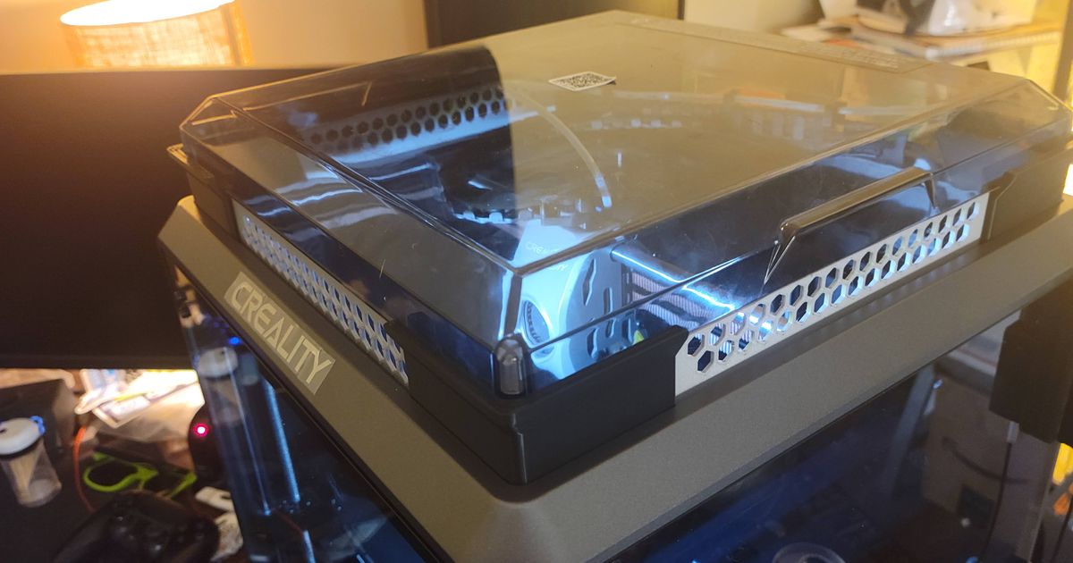
The Creality K1 is a great machine, but there are a few things that needed to be upgraded. The factory LED strip is tiny, and although it does get the job done, it is severely lacking. There are a few risers available, but Joe Coopers was by far my favorite. Using his models, I modified the corners by adding a 45º ledge to the inside top of each corner. I also made my own "Betweeners", that match the profile of the corners and they also have a 45º ledge on the inside. The 45º ledge is used to glue a thin LED strip or in my case LED Modules, which will point towards the bed.
The factory LED strip is 24v DC, but the LEDs I had were only 12v. I ended up using a MP1584EN Mini Buck Converter, to drop the voltage to the needed 12v. I needed a place to store the buck converter, so I modified the front right corner, which is where the factory wire is, to be big enough to store some wire from the LEDs as well as the connector from the factory plug. The factory plug is a 1.25mm JST 2 pin male, so you'll need a female connector to connect to it.
I used a UV Activated Super Glue to glue the parts of the riser together, and to glue the LEDs to the ledge. I replaced the factory M3 socket cap screws with M3x30mm screws so the magnets on the lid still keep it in place. I also placed a piece of the soft side of a velcro strip on the left side betweener so that the chain doesn't bang on it while printing.
JST Connectors - https://a.co/d/4JkmR9O
Buck Convertor - https://a.co/d/cUawXn1
LEDs - https://a.co/d/cH67mPD
M3-0.5x30mm - https://a.co/d/fA1qX13
UV Activated Super Glue - https://a.co/d/iah0Dnf
Assembly:
The "Kit" file has all of the parts needed for the build, or else you'll need to print ...
One (1) of Each Corner
Three (3) Betweeners
One (1) Back Betweener
One (1) Lid
Note: If you are not going to do the led mod, then print two (2) of the Front Left Corner.
Note: If you are going to use 24v LEDs, skip the part of the buck converter, the wiring should still be important to read through.
After everything is printed, remove the top lid, and proceed to remove the Four (4) M3x4mm Socket Cap Screws. These don't hold anything together and are only needed so the lid has a place to sit. Let's do a dry fit before glueing. Place each corner piece in there respective spot, keeping in mind the one with the recess is the Front Right and The Rear corners only have the ledge on the side and not on the back. The Right Rear corner also has the angled notch for the Bowden tube. Place each betweener in their respective spots, the rear betweener has no ledge and has a notch. If everything fits properly it's time to glue it up. On a flat surface, place all the pieces in order so nothing gets mixed up. Using the UV Super Glue, place a few small drops of glue in a notch of a corner piece and glue the respective betweener. place them on the flat surface standing up, making just the joint is tight. Place the UV light top down so the glue can solidify. after 10 seconds the glue should be cured enough to turn it upside down and place the light on the bottom to guarantee you got it from both sides. Now lay the joined piece so the outside face it on the table. Place a few drops of glue in the inside seam of the joint to reinforce it. Repeat this for the rest of the pieces.
Once you are set to move on, it's time for the LEDs. Feel for the wire from the top right corner of the machine to factory led strip. When you have a good grip on it, gently pull away to the side of the machine to not damage the connector. If you pull towards the build plate, you'll damage the connector on the original strip and the wire itself. Once it's free, carefully connect the new female pigtail to the factory connector, make sure the ends do not touch. You'll need to check the polarity of the wire to proceed from here. On my machine, the + / - were reversed, so you'll definitely want to make sure. When you figure out which is which, remove the pigtail and solder the leads to the buck connector in the respective spots. Plug the buck converter back in, and with your voltage tester, test the output voltage. Use the potentiometer on the buck converter to adjust the voltage to the range to meet your LEDs needs. Disconnect the buck converter and finish wiring up the LEDs. To glue the LED Modules, I used the same UV Super Glue. I pooled some glue placed the LED Module on top of it, and cured it. Repeat for the rest of the LED Modules. When you're all done glueing up the LEDs, place the riser back on the machine and connect the wires to make sure everything works. Neatly place the connector in the recess and put on the lid. The excess wire from the factory plug can be tucked into the top right corner as shown in the pictures.
Print Settings
Printer: Creality K1
Rafts: No
Supports: Yes
Resolution: Standard 0.2mm
Infill: 50% Gyoid
Filament: Inland - Black - Tough PLA
Notes:
Sliced with Creality Print with the Default K1 Profile
Printed on a Creality Textured PEI Build Plate
230º/60º
Shell: 5 Walls
Supports: Strong Tree Supports
Support Placement: Everywhere
If you have any warping, use an 8 line brim. The 3 of the corners only need supports for the hole on the bottom of the model, and pop off fairly easily with the small screwdriver that comes with the machine. The Front Right Corner needs supports for the ceiling of the recess. The Back Betweener needs supports for the notch.