Gaggia Classic | Pro Scales
Gaggia Classic | Pro Scales


Print Profile(1)

Description
This assembly is for adding scales to your Gaggia Classic or Gaggia Classic Pro.
Compatible with two HX711 boards or Vas' dual HX711 board. Requires 750 g load cells.
There are limits to what can be done with instructions here. Clearer instructions are available at https://gaggiuino.github.io/#/accessories/hw-scales
Hardware needed:
- M3 Flat head screws
- 2 M3x5 mm nickel plated steel (must be magnetic)
- 6 M3x5 mm and 4 M3x4 mm (non-magnetic stainless steel)
- 2 thread-rolling/self-tapping screws for plastic (multiple options, pick one)
- M3x6mm self-tapping screws for plastic
- #4-20x1/4" thread rolling screws (local USA option)
- M2.9x6.5mm self-tapping screws for plastic (local EU option)
- 20 disc magnets, 5 mm dia. x 2 mm ht.
- https://www.aliexpress.com/item/3256803930463196.html
Note: Most machine housings are magnetic - you only need 12 magnets if yours is not. The scales will still work but won't be held as securely.
- https://www.aliexpress.com/item/3256803930463196.html
- Gap-filling cyanoacrylate (super glue)
- 2+ 750 g load cells
- https://www.aliexpress.com/item/2251832483911236.html
Note: Buying 3-4 load cells is recommended as QC isn't great and they may need modifications that can result in damage if done improperly
- https://www.aliexpress.com/item/2251832483911236.html
- HX711 interface board(s)
- https://www.aliexpress.com/item/2251832855509243.html
- 2 AliExpress HX711 boards OR
Note: you may want to buy 3 as some people find them tricky to solder - 1 custom dual-HX711 board from the Gaggiuino project
- 1 row 2.54 mm right angle (reverse bending) header pins (only need 5 pins)
- 1 5P JST XH or DuPont connector
- 1 Stripboard/protoboard (only need a small piece)
- 26 or 28 AWG Wire in Black, Red, Yellow, Blue
(only uses ~1 m ea. if you're extremely efficient, order extra to be safe)
NOTE: if you use the Vas DualScaleBoard you don't need the resistor
- 1 1KΩ resistor
Print Instructions:
Print all parts in “Base” folder. Note that you need 2 Flex Limiters and 2 Load Plates.
There are 5 main drip tray options. Any of them will work with the scale base, pick one:
- GC Drip Tray: GC Drip Tray Adapter and 4 Drip Tray Spacers
- GCP Drip Tray: GCP Drip Tray Adapter (L and R)
- Low Profile 3D Print DripTray (no other adapters needed)
Note: Recommend printing the _testSupport model and verifying quality before printing the 3D Print DripTray LP. Also, ensure excellent bed adhesion to avoid warp at the edges. - Low-Profile Drip Tray: LP Drip Tray Adapter and 4 Drip Tray Spacers
Note: designed for BaristaGadgets and Shades of Coffee (Pre 2019) low profile trays (may be compatible with others, but unconfirmed) - 3D Print DripTray / LP (no other adapters needed)
Note: not recommended unless your stock tray is broken
Flat first layers are essential because clearances are so small. If you have flow issues such as elephant's foot please calibrate flow before printing or parts (magnets, load cells) may not fit.
Print settings: PETG, 0.2 mm layer height, 0.4 mm nozzle, no support, 20% gyroid infill. 3-4 wall lines recommended for GCP drip tray adapters. Print orientations per model.
Printing notes:
Minimum print area is 150x150 mm
3D print drip tray requires 200x130 mm print area. A thin coat of epoxy resin / clear coat will help make it waterproof if your print has slight gaps left.
Assembly Instructions:
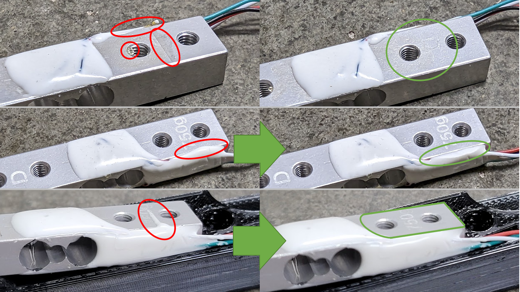
- Clean up load cells - The load cells I got came covered with adhesive in places it shouldn't be. Use a sharp razor blade and cut the adhesive away from the screw holes, being careful to not cut a wire or cut into the load sensing area.
- Fit-up the load cells into the housing, re-trimming adhesive if necessary. If you went with the 2 different M3 screw lengths, use the 5 mm screws on the top to attach to the load cell housing and the 4 mm screws on the bottom to attach the flex limiter. Attach the load plate using one magnetic screw as noted and make sure there's a gap all the way around.

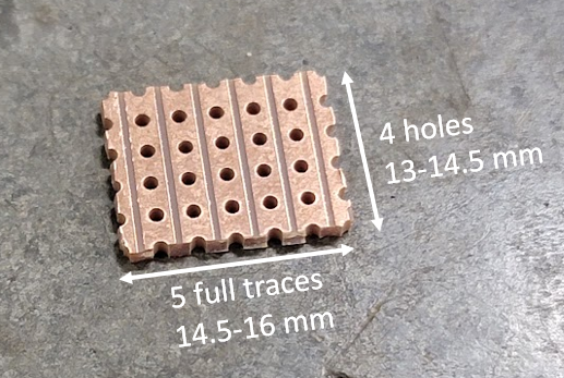
- Cut the stripboard to size and cut off a group of 5 right angle pins
- Do a quick fit-check with the base assembly. Note that the load cell housings are designed to be slightly loose so that parallelism issues in the sheet metal don't affect them. Slide the PCB retainer to check that the boards lock in.
- Cut the load cell wires as shown (this provides extra for strain relief) and save what you cut off
5.01 - DualScaleBoard only - cut the JP11 jumper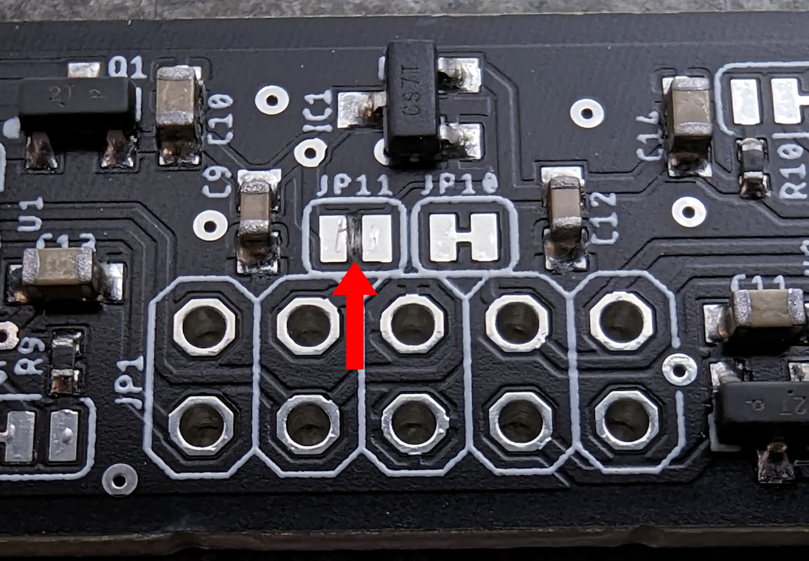
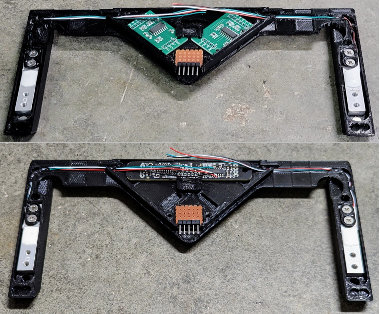
- Use the leftover wires to solder the stripboard (the resistor is a 1kOhm SCK pull-up, not used with the Vas DualScaleBoard). Fit the board back up, measure wire lengths to the board (with extra) and cut to length. If necessary, trim backside wire tails so that the board fits in the housing.
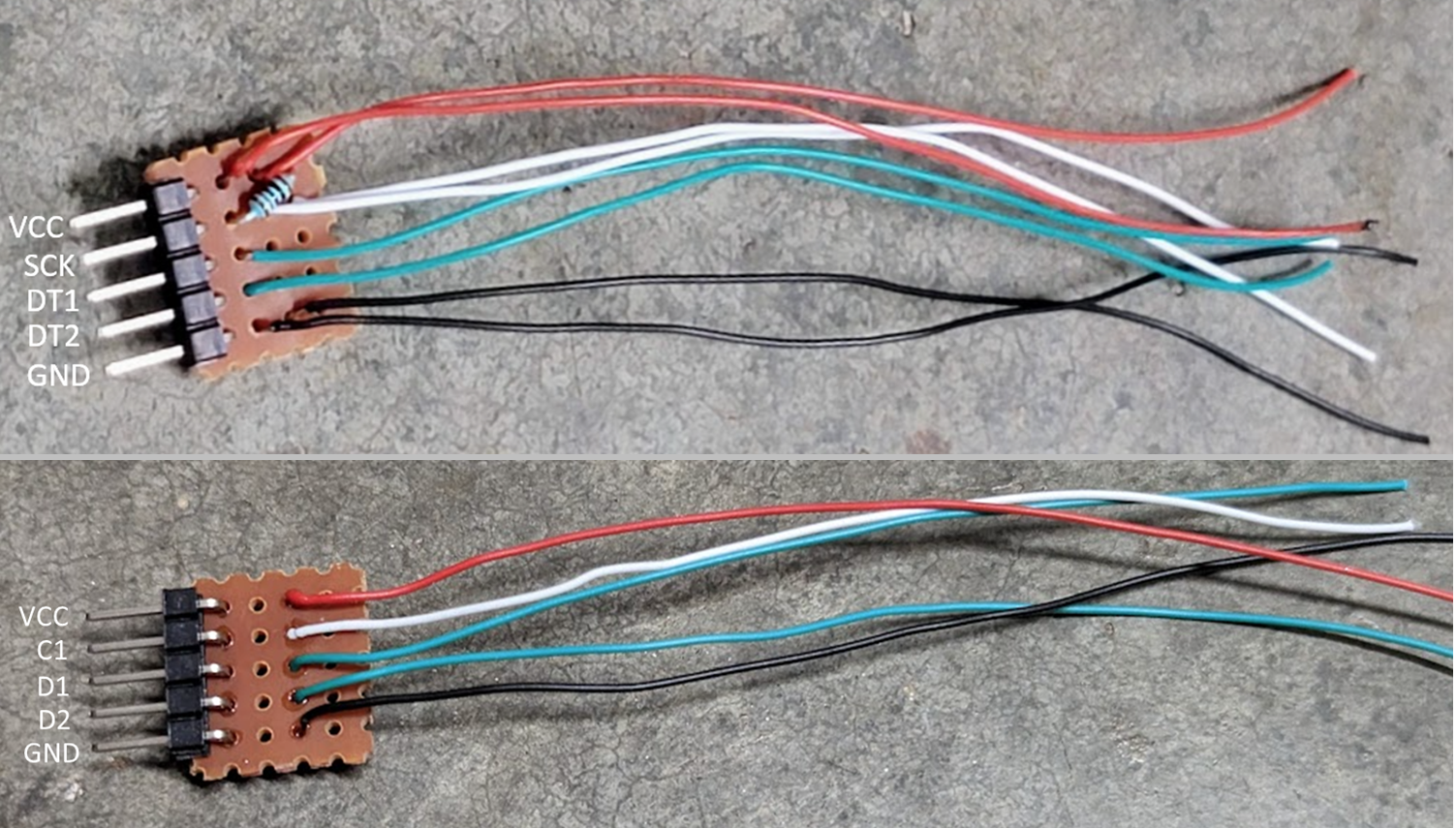
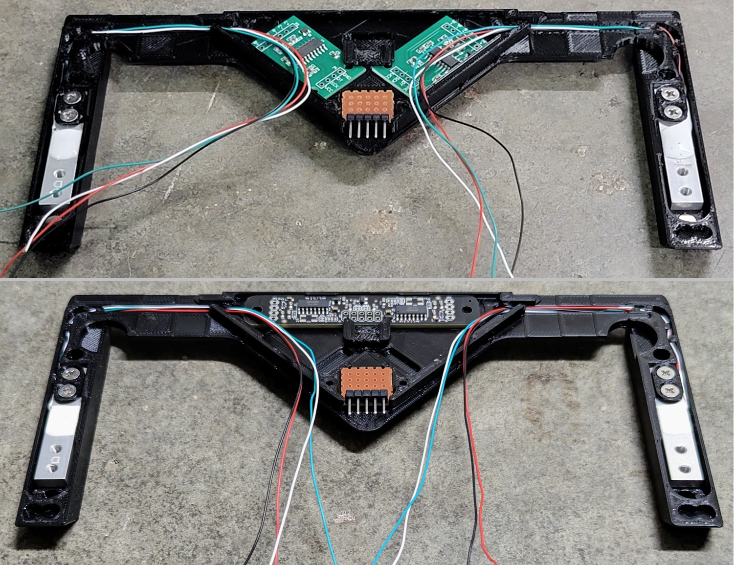
Build for Vas DualScaleBoard shown on bottom (note no resistor needed)
It's fine to make the wire order line up with the DualScaleBoard. I chose not to do so because I wanted my scale builds to be interchangeable.
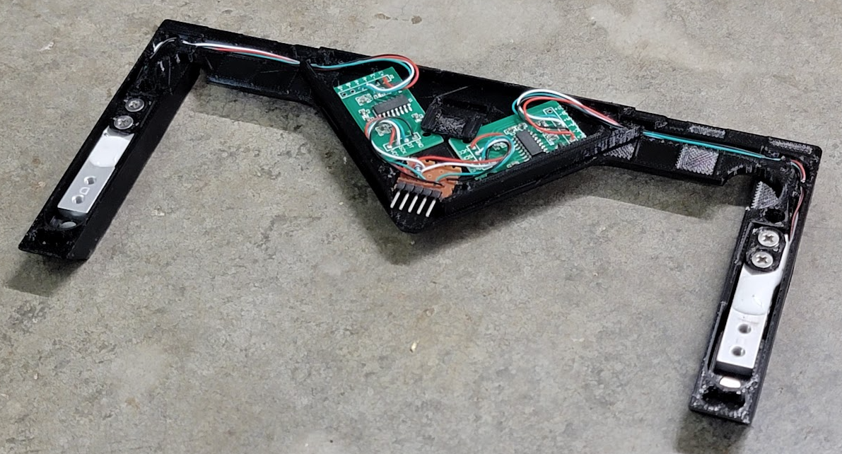
- Now that wires are all cut to length, remove the boards from the housing and solder (don't solder in the housing, you'll melt it). When you're done it should look something like this:
Purple HX711 boards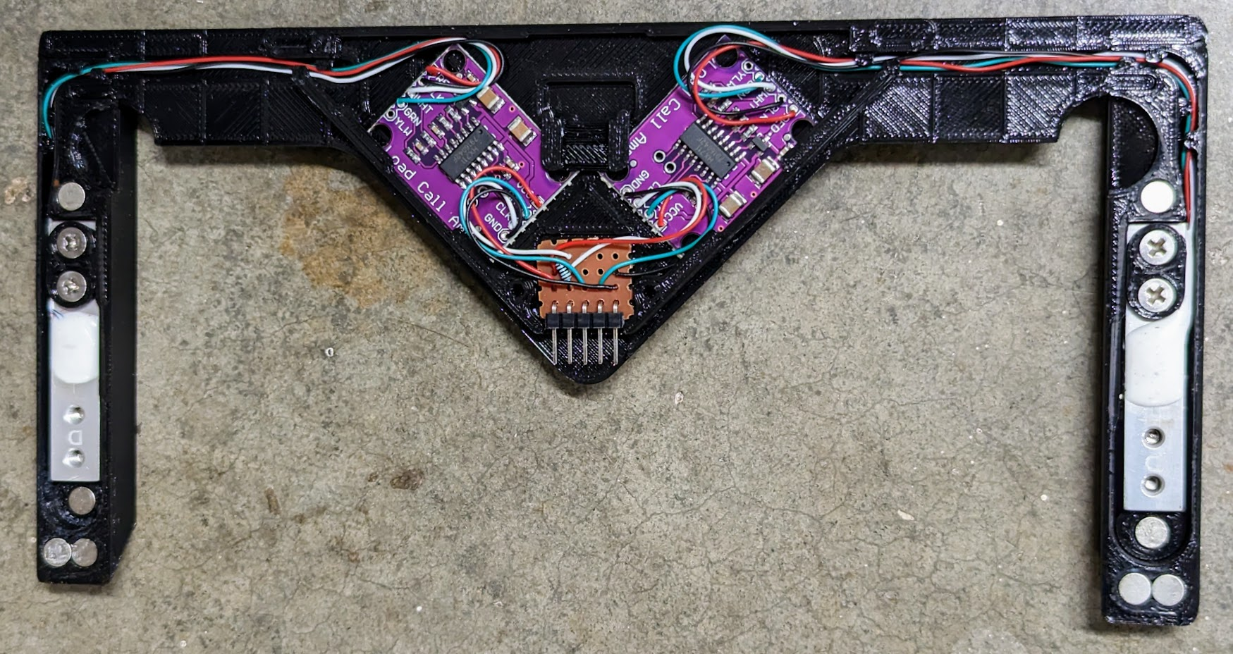
Vas DualScaleBoard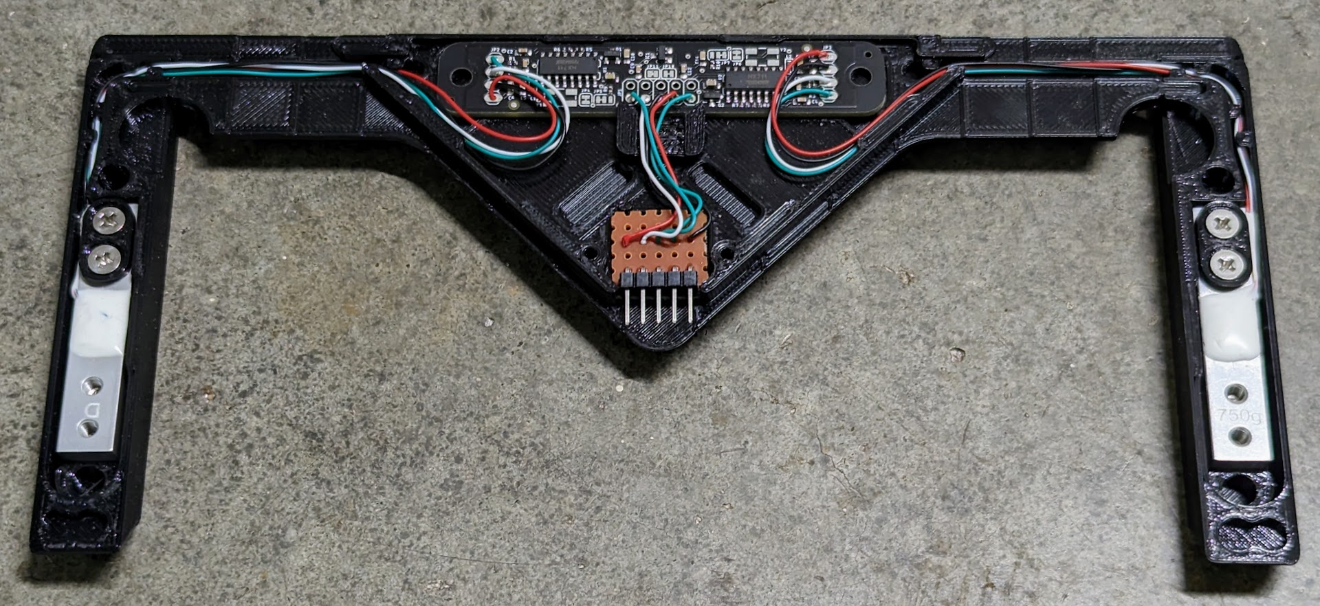
At this point you can attach the center housing cover (slides on from the front) and screw it down with the 2 thread-rolling/self-tapping screws.
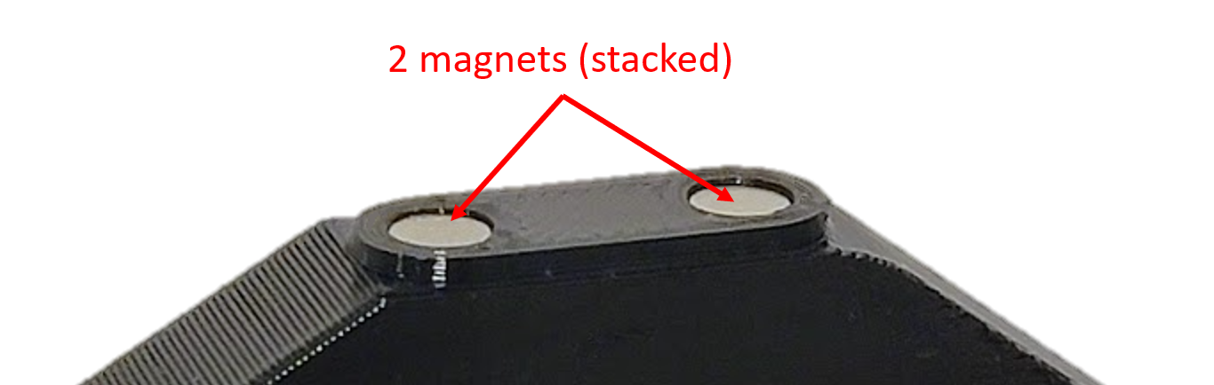
- Install magnets in load plates, load cell housings, and drip tray or drip tray adapter parts using the gap-filling cyanoacrylate. Holes are sized to only have 0.25 mm extra depth, so if a hole looks like it could fit another magnet put another one in. Make sure to match polarity of magnets on the drip tray adapter and the load plate so that it snaps in place.
Note: If your magnet holes are undersized, brush over the edge with a hobby knife to slightly widen the hole, then partially insert the magnet manually. Press down on a flat surface to seat flush.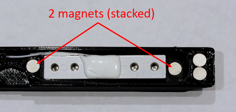
Note: If you're using the old GCP Drip Tray Adapters and Clamps it's easier if you install magnets in the order shown below. Otherwise, the bottom magnets can spin the internal side-facing magnets as you try to install.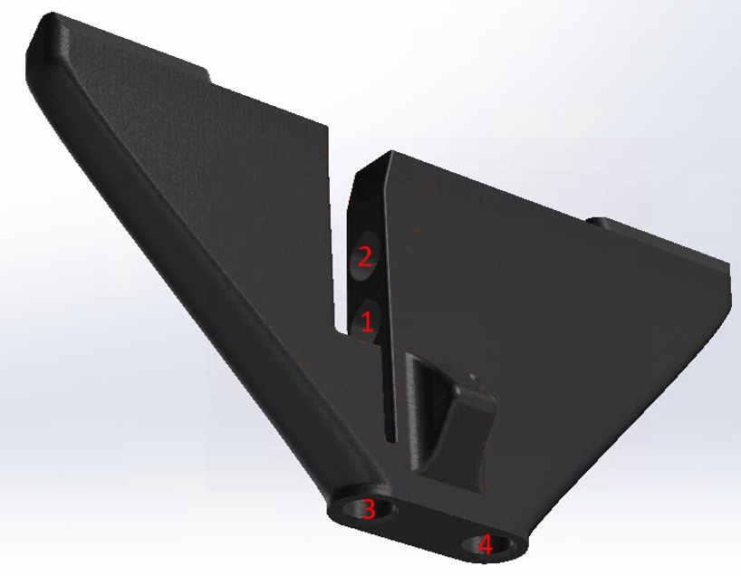
- For GC and LP drip tray adapters only:
Fully insert the drip tray spacers into the drip tray adapter with the flat surface down. If the fit is not snug use a drop of cyanoacrylate to hold each spacer in place.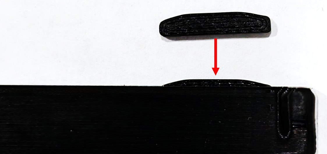
- For GCP stock drip tray only:
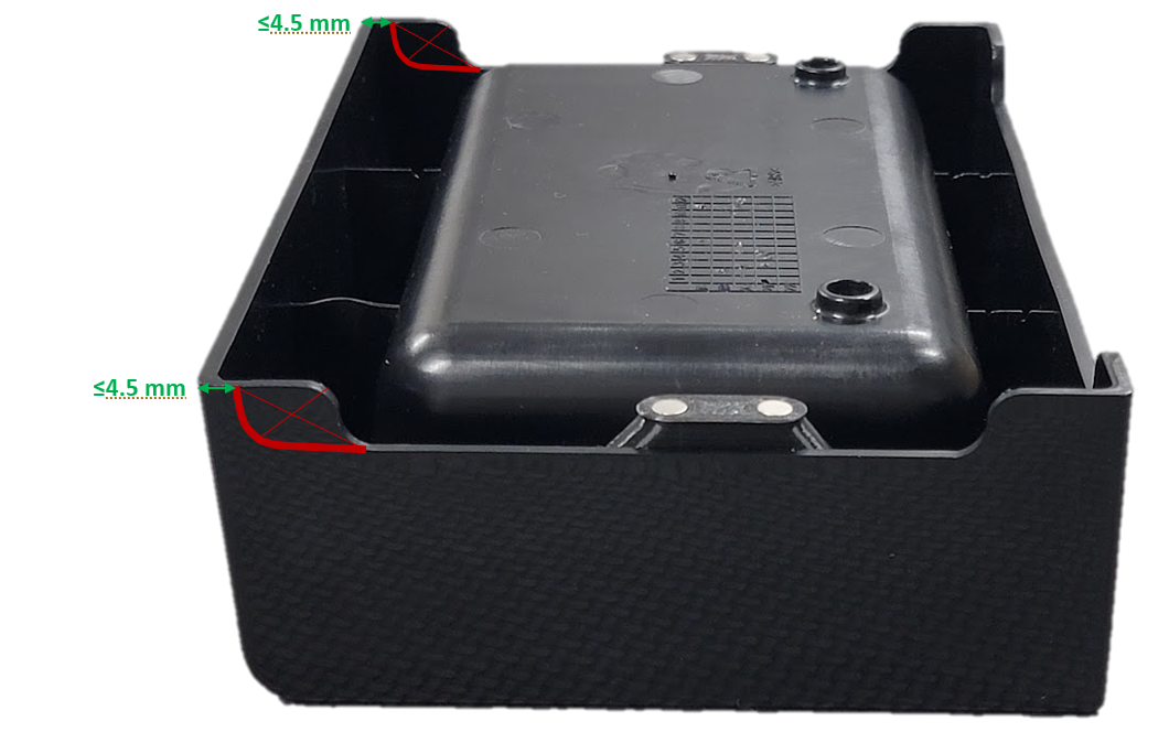
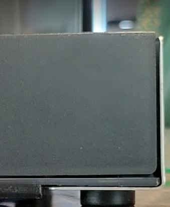
- Cut the sides of the drip tray as seen below (thick red line) and remove scrap (red X area). This provides clearance to the load cell housings.
To cut the profile I sketched on masking tape, did a pilot hole, used a step drill bit for a 5 mm radius (10 mm diameter), cut with a hacksaw, and then finished with a hobby knife and file.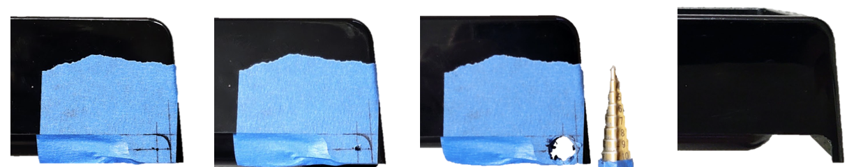
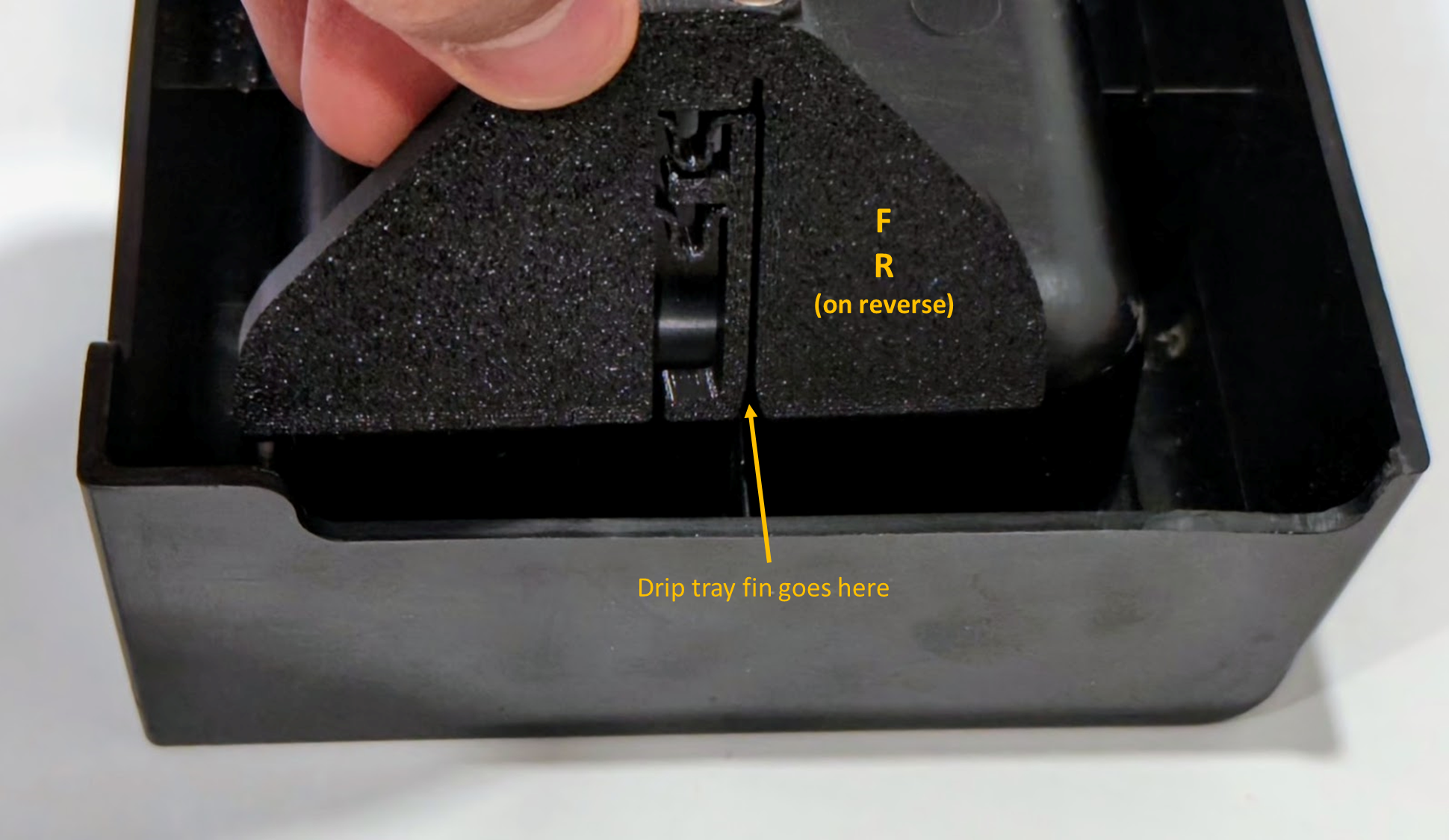
- Slide the drip tray adapters onto the drip tray side fins. The adapters are labeled F (front) and L (left) or R (right), left/right orientation as if facing the espresso machine. Make sure the adapters are fully seated on the underside of the tray's top surface.
(old version)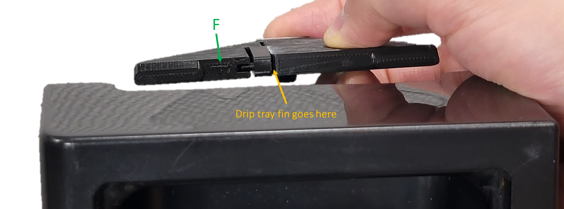
- Cut the sides of the drip tray as seen below (thick red line) and remove scrap (red X area). This provides clearance to the load cell housings.
- Wire a 5P JST XH or DuPont connector (I used JST XH with the latching features cut off because it'll only fit one way with enough clearance to install under the machine) and route through the housing back to wherever your controller is. Protect the areas where it goes through the housing with heat shrink tubing and ensure the wires don't affect placement of the water tank so much that it rubs the drip tray.
Note: ignore wire colors seen below, follow Gaggiuino schematic coloring (Red: VCC, Black: GND, Blue: DT, YLW: SCK).
- Place the assembly into the machine and check fit. Things to verify:
- Load cell housings are parallel to each other and the Gaggia housing sides
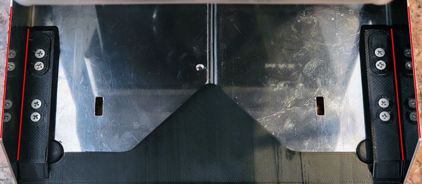
- Drip tray or drip tray adapter fits with even gaps around it, not touching Gaggia housing sides or water tank
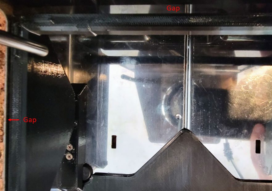
- Drip tray has at least 0.5 mm clearance under the front lip and on the sides
- Load cell housings are parallel to each other and the Gaggia housing sides
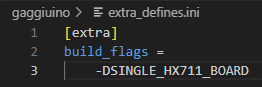
- A. DualScaleBoard only - before building in Platformio, create an “extra_defines.ini” file with these contents in the project root (can copy from platformio.ini).
B. Use the appropriate scales-calibration task to upload to the STM32 and copy scales-calibrate TFT onto a microSD card to flash the Nextion. You should see this show up on the screen (with numbers).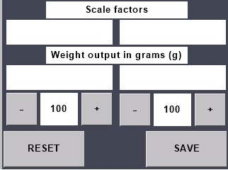
C. Remove the load plates and calibrate load cells using the calibration load plate to space the load away from the load cell housing (otherwise the housing will take some of the load). I prefer to detach the load cell housing from the center housing as shown to get more room to fit the calibration weight (in this case a 318.5 g tamper). Ideal calibration weight is in the 200-400g range.
D. Adjust the scale factors until the weight output matches the real weight (positive value). Take a pic or copy down the scale factors.
Note that due to the mirrored load cell housings one scale factor will likely be positive and one negative to make the output (g) positive for both.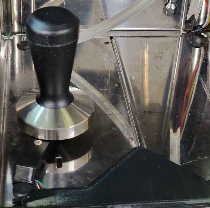
E. Copy your the scale factors into the LC1 and LC2 Factors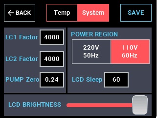
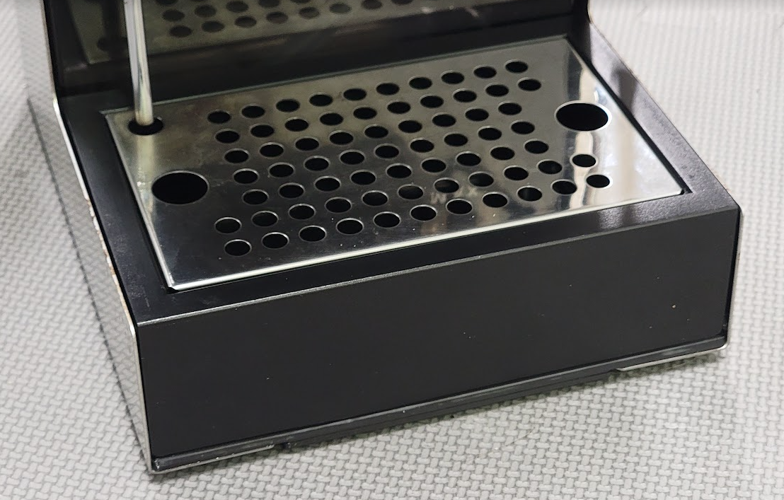
- Add the drip tray / drip tray adapter. Congrats, your machine has a scale!
Troubleshooting:
If you have “jumpy” scales or are struggling to calibrate, check that
- magnets are installed flush or sub-flush
- the bottom surface of all parts resting on the machine sheet metal is flat and free of dirt, dried adhesive, print artifacts, etc.
- the load cell adhesive is not clamped by the load cell housings or flex limiters (see step 1). Adhesive on the side of the load cell before the cutout area is fine.
- the load plates have clearance to the load cell housings all the way around
- wires are not routed by high voltage
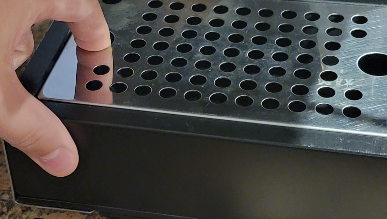
Note: If using the stock GC|P drip trays you may want to file or cut 2 mm off of the pressure outlet tube (solenoid vent) to bring it to 130 mm and make drip tray removal easier.
Also, you'll find that you might not be able to easily reach under the stock drip tray to remove it - I find holding it like this to lift over the retaining lip and pull it forward slightly works well.