


Print Profile(1)

Description
Doors for Ikea Kallax shelf units with replaceable inserts. No holes or modification to the unit required.
Before starting, I want to stress that much of the hardware used is pulled from stuff that I had on hand and the design is based around the left overs from previous projects and old hinges that needed replacing in my kitchen. The full Fusion design is included in the raw model files for those that want to adapt to the hardware they have. The total cost of each door is about the same as the inserts that Ikea offers, around $15 USD. This isn't a project to save money but to create a personalized and custom look.
Goals:
- flush door
- push to open
- nondestructive to Kallax unit, no holes added
- replaceable inserts
- install slow close hinges on my kitchen cabinets (overlap from honey2do list)
Print Plates:
- Door Jamb ~38g (Bambu PLA Matte Ivory White)
- Door Frame ~230g (Bambu PLA Basic Black)
- Insert ~135g (Bambu PLA Matte Ivory White + color)
Printing:
- Full size (256x256) print bed required
- Brims are used and recommended for the panels. The doors are designed to be flush with the unit with minimal gaps. Even small warpage with PLA could lead to scrapped parts and wasted time.
- No support needed
- Hinge openings are tear dropped for the overhangs. (Still learning 3d printing and circle pockets were printing rough for me)
Hardware BOM that I used:
- 3-5x Command Strips, Poster size (small size)
- 2x M5 hex nuts for hinge to door jamb (could be M4 or M5 heat set inserts)
- 2x M5x14 FHCS (flat head) to match above
- If using SHCS or BHCS (socket or button head) use 10mm lg
- 8x M3 inserts
- 4x M3x12 BHCS (button head) or SHCS (socket head) for hinge to door panel
- 4x M3x8 FHCS (flat head) to connect door panel halves
- 2x Hinges …. scrapped from my kitchen cabinets… TBD see below
- 1x Door latch/opening spring, ones used were $10USD pack of 4 (https://www.amazon.com/dp/B0CKX4X2YR)
Step 1:
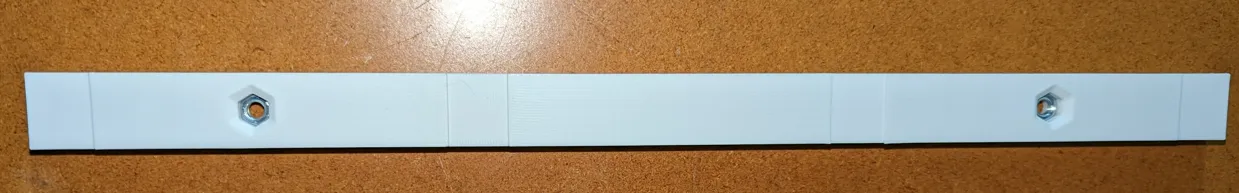
Print door Jamb.
M5 hex nuts are interference fit, so place nut in the opening and tighten to seat inside of jamb pocket.
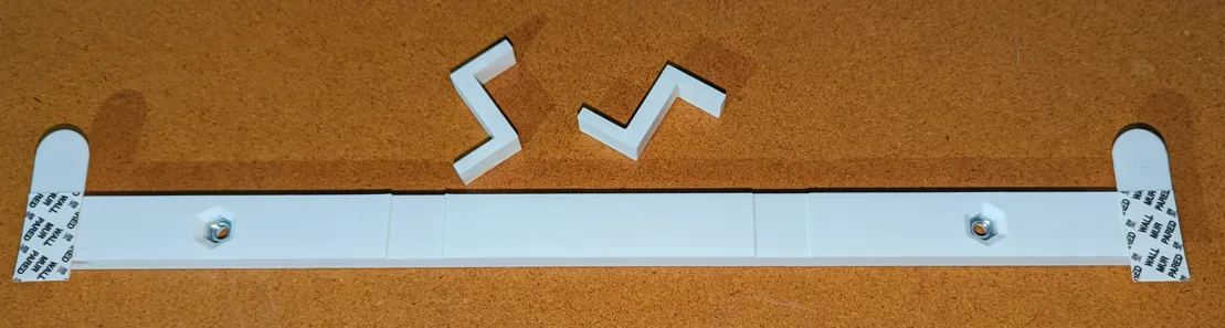
Remove the “poster” side of the command strips and place on door jamb. There are 4 spots for the strips, I only used the ones on end but there are room for 4. This is where I should note that these have only been installed for a week so additional are added in case I see adhesion issues in the warmer humid months.
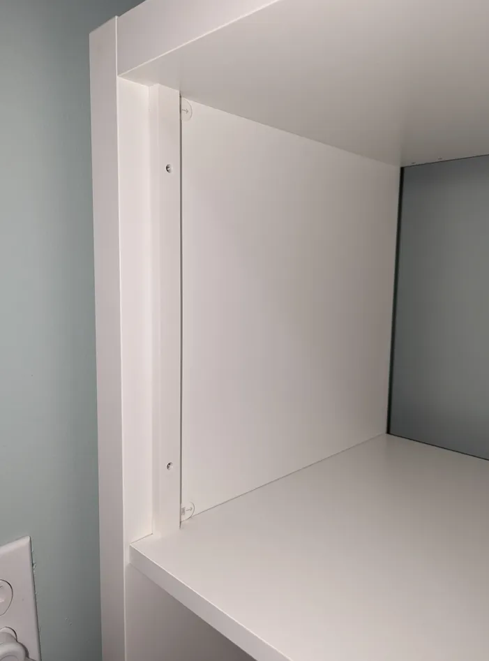
Peel the wall side film off of the command strips and stick to wall of the Kallax unit using the included set tools.
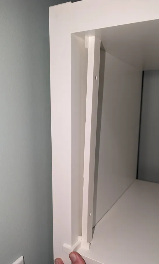
The jamb should be a tight fit in the opening and allow for positioning before the command strip sticks to the side wall.
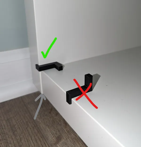
Important: Use the gage tool on the side of the unit that is the widest (see 2nd image)
Rough alignment of the jamb shown to set the depth and squareness. Once top and bottom are set with the gage, the lower end is pressed against the wall, then upper set using gage. Hold pressure on both ends for 30 seconds.
Note the small lip identified below. Tool is used on the widest member of the unit. Do not align with one of the interior members that are inset from the outer most edge.
Step 1 complete
Step 2:
Assemble Door.
Install M3 inserts:
(2) in each half for the hinges.
(4) M3 inserts in the panel half that has blind holes on the ends
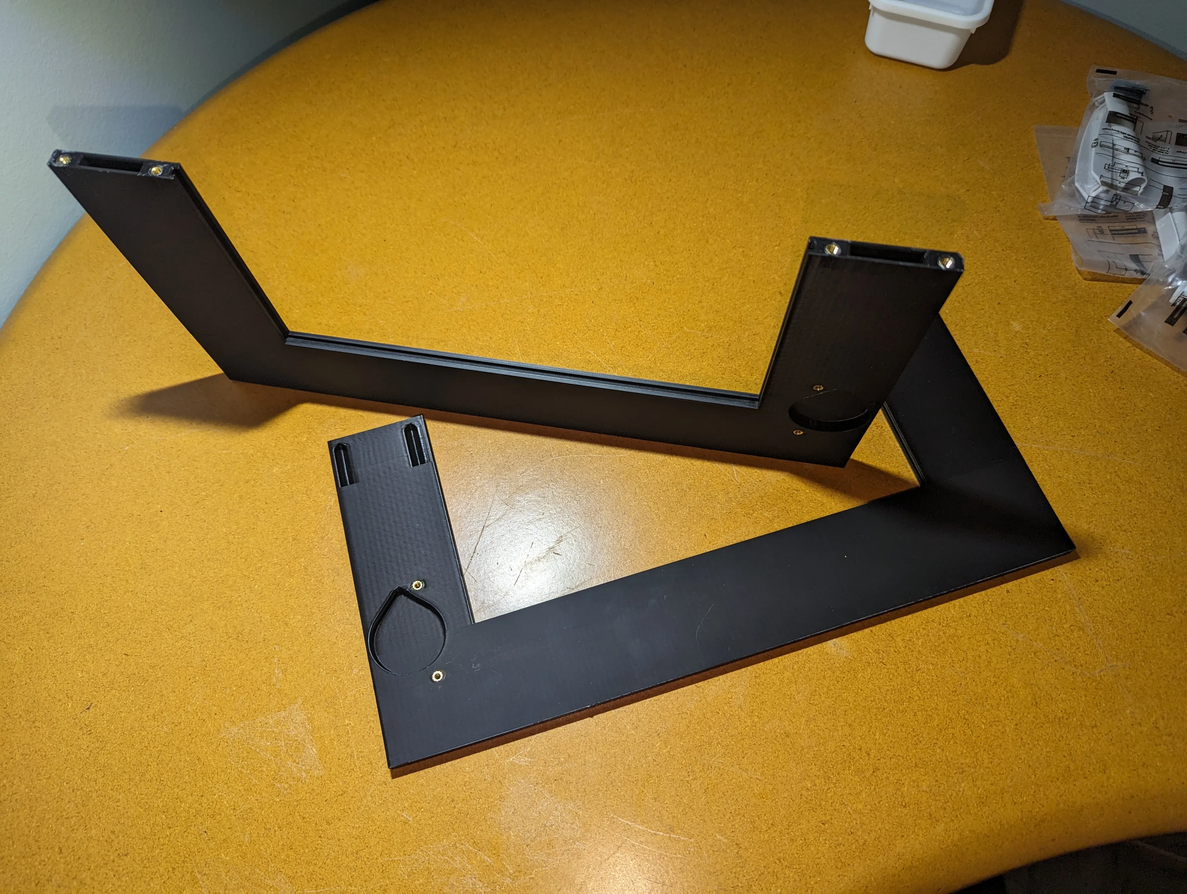
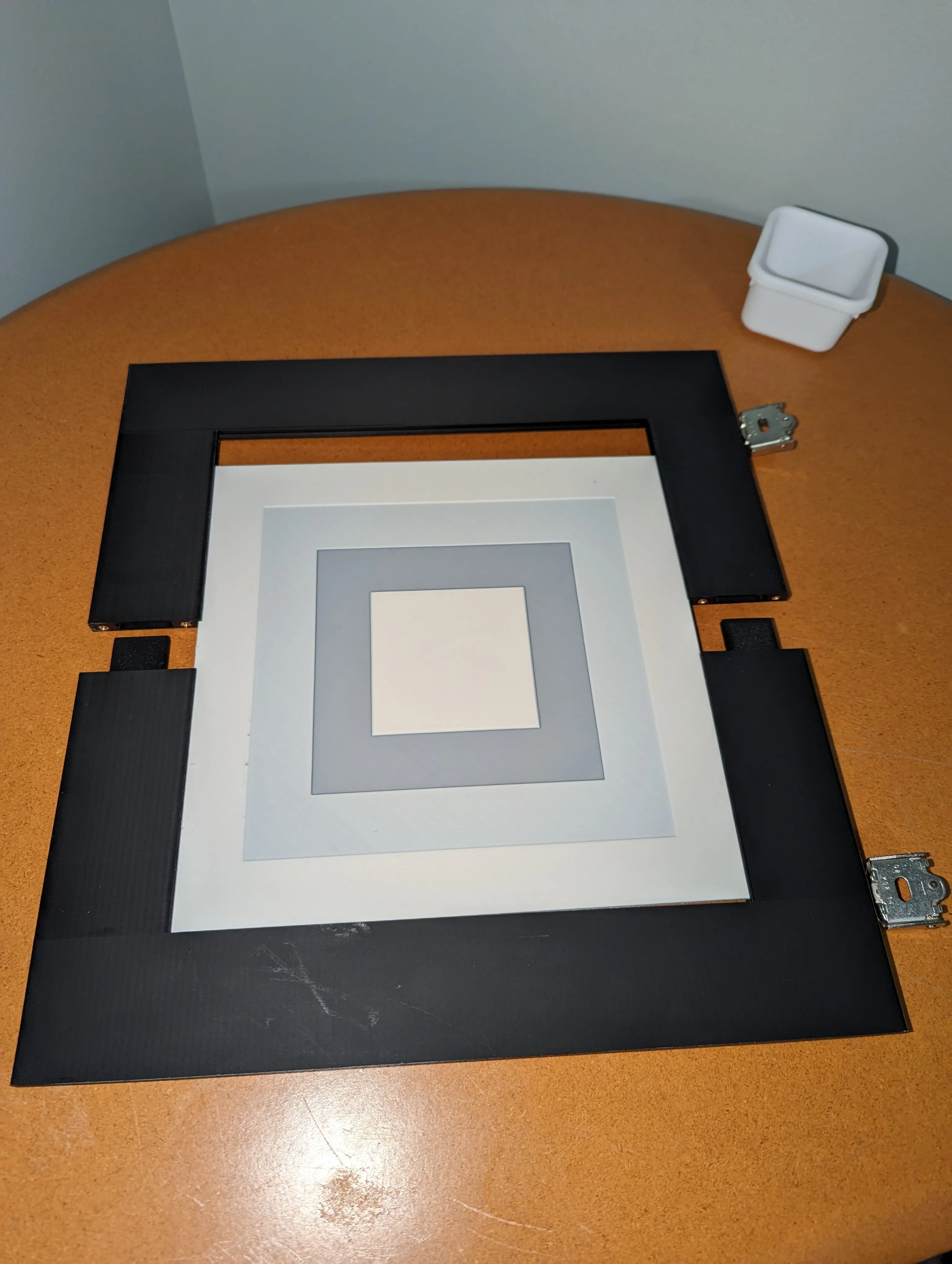
Slide the 2 keys into one of the panel halves and your insert into the middle groove
Slide the other panel half over the insert and secure with (4) M3x8 FHCS (flat head)
Install the hinges into each pocket with spacers and M3x12 BHCS
Step 3:
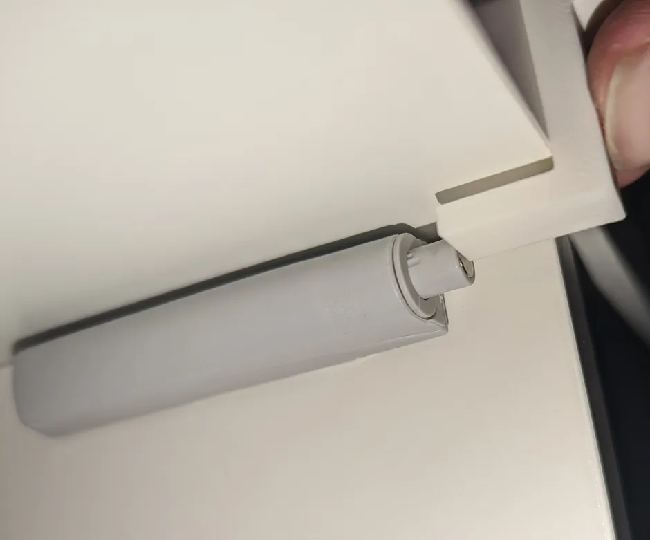
Install the opening latch.
Instructions will vary based on the latches you have. For the ones linked above, a single poster sized Command strip can be used. Turn the barrel of the latch to roughly center it on the center of its adjustment stroke. The shorter end of the set-up tool can be used as a guide for positioning it.
Step 4:
Use 2x M5x14 FHCS or M5x10 SHCS/BHCS to attach the assembled door to the jamb.
Step 5:
Adjust the hinges and latch to square the panel in the opening and remove any rubbing.
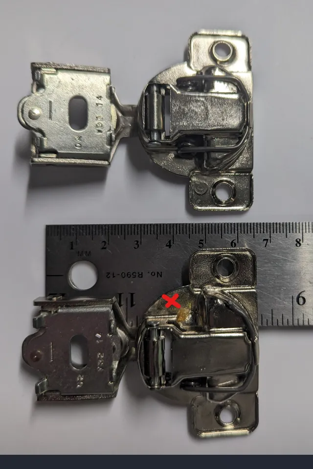
Hinge Notes:
½" inch overlap hinges were repurposed for my build. These appear to be a standard size; but for those in need of some specifics:
Critical dimensions used in the design are a 45mm hole spacing to the panel and a cup diameter of 35mm. Cup depth for 10.8mm was used without any issues. The a deeper cup depth can be easily accommodated with the hinge spacer. (A thicker spacer is included in the raw files that is 0.8mm thicker than the main to bring the cup depth to 11.6mm, if needed).
I believe hinges of this size would work:

(source: https://www.amazon.com/Chibery-Overlay-Concealed-Adjustable-Stainless/dp/B09TZQ5P5S )
Since repurposed hinges were used, I cannot verify or provide a specific BOM item.
If you happen to have cabinets in your house that use this style hinge, I would suggest buying the amount needed for any worn out hinges you already have and repurpose the old ones into this project.
I found that while my decades old spring loaded hinges were to worn out for wooden cabinet doors they were a little over powered for these lightweight prints.
I snipped one of the springs to reduce the closing force.
The “slow close” hinges should work fine or better, but I did not test.
Feel free to comment with hinges you used and your experience with them :)
Insert size: 236x236x2.8mm
Sized for maximum print space on the full sized printers.


