I tried to find a GOOD kinetic wall art model that neither costs a few hundred Dollars NOR would require magnets.
And as it can be hard to find those 'constant force springs' for a good price....
Designing the basic model was done in a few hours, making it work as planned took a few weeks and, if I recall correctly, about 4 rolls of filament.
So what was the goal here, apart from being a proof of concept model that actually works ?
Update: The large model is now tested - runs for over 20 minutes....
Simplicity!
No tapping for screws, only a single M8 or 5/16 bolt and nut is required.
Only three 608 bearings, not 4 or even 6 like in some models out there.
Uses two springs and the cage taken from a $2 sewing tape measure.
Did I mention NO SCREWS already ?
All the levers and winders are fixed in place with pins ;)
There will be updates to the files, video and of course some pics - just give me a few days as I am currently testing the LARGE version of this model - it will be included in the files.
A LOT of work, filament and frustration went into making this model.
The asking price is more than fair IMHO as this model will be maintained and updated with more spring options, including 8m ones for a much longer runtime.
Basic assembly instructions for those early birds out there:
Front and back plate are identical but the release levers are mounted differently.
For the plate on the back:
Use the LEFT hole (if the blocking ramp is located at the 12o`clock position.
The pointy bit of the lever aims to the RIGHT.
For the front plate use the hole on the RIGHT side and have the lever pointing to the left.
The pins have a larger cover on one side, have this supporting the lever.
The pins should be of proper length but if you push really hard the lever might not swing freely.
You can prevent this by putting two strips of paper between the two when pushing the pin in.
Mount the arms - it is a TIGHT push fit, if it is too tight just gently sand off the edges of the arm - only the ones you push in, not the top ones.
I use a little block to provide even pressure once the arm is straight and tries to go in.
There should be no need for glue....
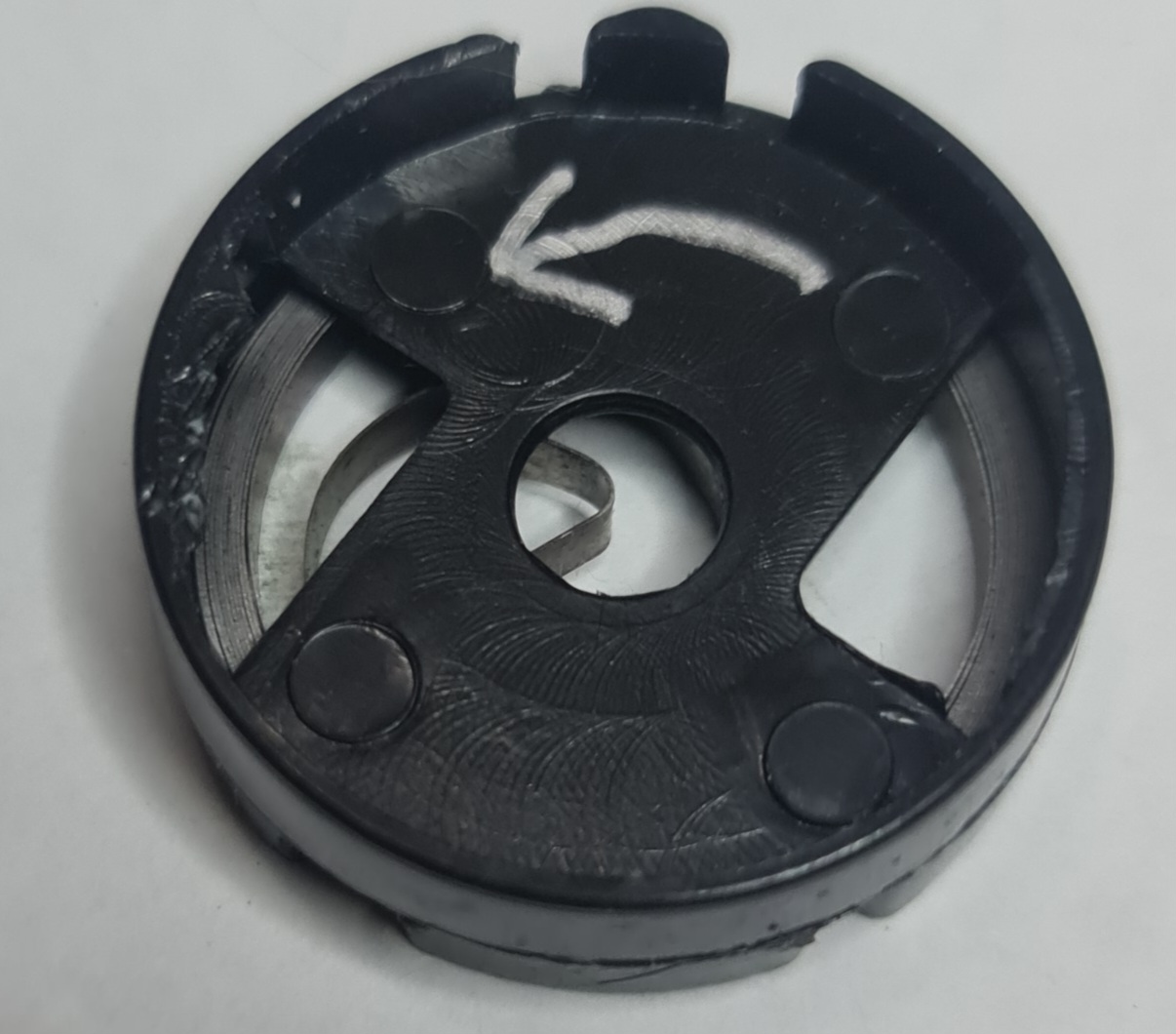
For the springs there is a cut out on the holder for the part of the original spring housing with the actual spring going on the outside to lock it in place.
The spring should be on the open side.
If the spring housing has a little triangle for the stopping mechanism then please break this out.
(Pics for this will follow soon)
The release gear assembly can't really be messed up.
Push the bearing in, push the winder ring over and cap it with other part of the release gear so the teeth are all lined up.
You can use misaligned gears for a different timing but this will require changing the balance points.
The spacers are for the release gear and if it does not spin freely and without binding to the front or back plate add a washer.
The power from the two winders is transferred using some braided fishing line - or strong sewing yarn, anything thin and reasonably strong will do fine.
Double check the winding direction!
The winder should spin COUNTER-CLOCKWISE in order to wind the spring up correctly!
That means you wind the line counter-clockwise onto it as well.
I use a simple noose knot and once tight add a drop of superglue to prevent the line from slipping on the winder - wipe the excess off!
The lines from both winders go onto the release gear winder.
Again use a drop of superglue....
Make sure the winders have some slight tension, if in doubt spin them once with the line so add tension.
Do not glue in those pins for the winders yet...
Balancing the model:
The back wheel is best balanced if the release lever JUST lets go of the gear if you push the release gear back just slightly.
When the front wheel engages with the release gear only a slight bounce should be required to free the lever of the back plate.
The arm to the LEFT of the release lever (on the back plate) should be in the 6oclock position when the back wheel is in the resting position.
Means if weights to balance the wheel confirm it works you replace this arm with one that has a denser infill or more solid layer to get the required weight.
The front wheel is less critical and allows for some freedom.
Ideal is about a quarter turn from the front wheel neutral position for the lever to engage with the release gear.
Later engagement can mean the system stalls, engage too early and the wheels might not always swing both ways for a while until getting a new push.
Find what satisfies your visual and runtime needs most with some added weight, once you found your perfect balance point replace the arm in the 6oclock (while the front disk is neutral) with an arm that has a denser infill or more solid layer to add the required weight.
IDEALLY you won't both wheels as balanced as possible so they spin freely and with an almost even speed for a long time.
It takes slightly more force to free the gear if the springs are wound up tight - I recommend only 6 to 7 spins of the front wheel (clockwise) to charge the system.
Pics to show the assembly will follow, so stay tuned!
For best runtime use ceramic bearing or just empty out some cheap 608 ones so the grease won't slow them down.
:format(webp)/https://fbi.cults3d.com/uploaders/33265350/illustration-file/f8dae696-710e-4443-ae1c-b35bd33d1bf8/Springy.kinetic.wall.art.jpg)


/https://preview3d-images.cults3d.com/tnlnz4ugmlupb8cfqs8u3e1l5avz)

:format(webp)/https://fbi.cults3d.com/uploaders/33265350/illustration-file/3372f8dc-6985-437b-9bef-5ccd023555dc/20240308_183047.jpg)