Detailed TD calibration step test for HueForge by @XavierFaraudo
Detailed TD calibration step test for HueForge by @XavierFaraudo


Print Profile(0)
Description
No changes from original design.
I report original description:
UPDATED 2023-07-25: Added a guide on how to use this test, plus other additional info. If you're interested just in using the test, don't read it whole; just read the “What is the Blending Distance (BD)?” section and do the steps of testing, but skip all "Additional Info" and "Advanced uses" sections.
On 2023-06-27, Steve from HueForge introduced the new “step test” calibration for the all-important TD in HueForge. This may replace the good “old” FilaScope, for which I made a screw-on version, the step test being faster and more accurate.
I liked that, and I felt like it could use some improvements: space for labels, a hole for storage (keychains, etc.), and more steps than 5. Funny enough, my older OpenSCAD Filament Swatch creator already had some (very little) dabbling with filament color blending, and was more than appropiate to enhance the test model. (The guide has notes on adaptation.)
The step test(s)
They have been made so each panel is adjacent to its nearest variations, so the rows (if more than 1 row) are read in alternate order, starting by topmost row from left to right. That is: the top row goes from left to right, but the second goes from right to left, 3r from left to right again, and so on, like the "snake" game. (The technical term is "boustrophedon", "as the ox plows".) That's because if all rows had the same order, it would be much more difficult to tell if there was a difference between the last panel of a row and the first of the following row.
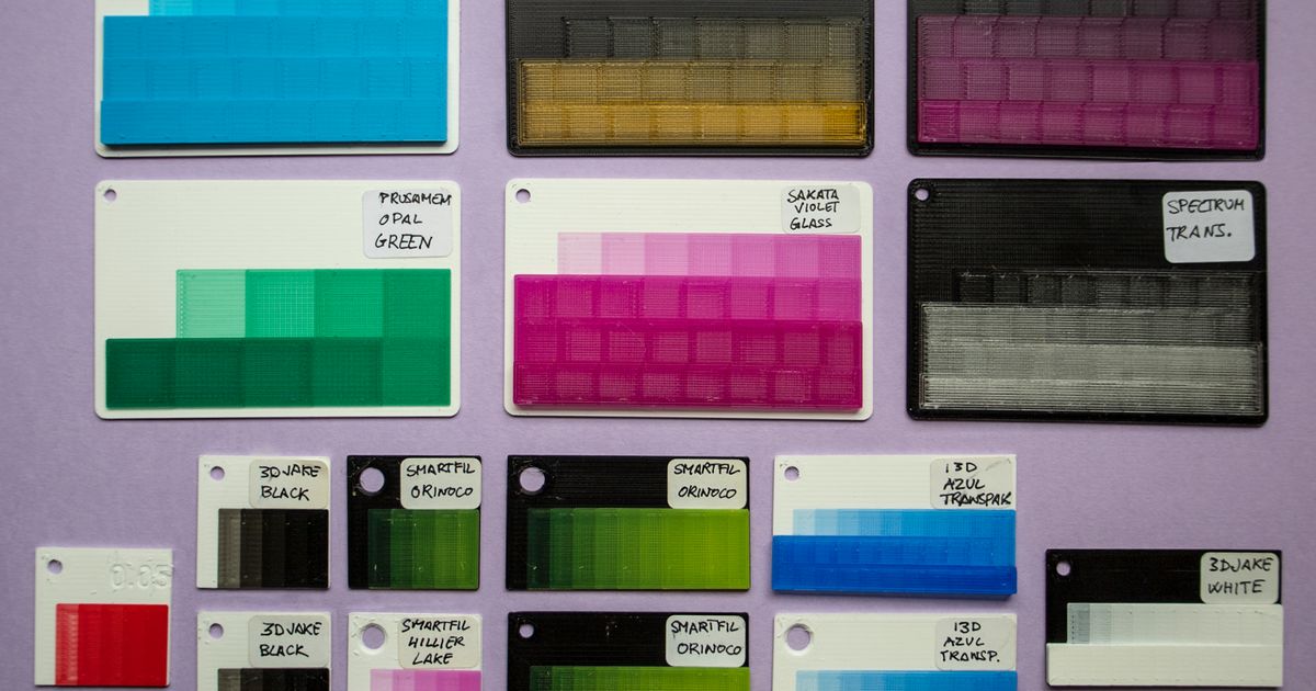
There are 2 size factors: small and card. They come in the original 0.08mm layer height and 0.05mm layer height, and have been named for the nearest number of steps (see below). They all have a flat panel-less strip on top for a label, and a 3mm nominal diameter hole (3.3 real) at the top left, spaced 2.5mm from the margins.
(An important note: In the pictures, some of the swatches have a hole "much" bigger than 3mm, as I was testing sizes. Anyway, in PrusaSlicer 2.6 is really easy to drill holes by adding a cylinder-shaped "negative volume" to the object; and you can use the "object coordinates" as reference instead of "World coordinates" (combo box above, left the coordinates and rotation). You then can export the plate contents as STL, and the STL will have the hole in it, so you don't even have to _slice_ in PrusaSlicer if you don't want to.)
The small version is 30mm “tall” (in depth, or Y axis), just like the original step test, but some variations are longer/wider:
- Step test labeled is 30x30mm with 5 steps (same size as the original step test), and a narrow top strip for the label.
- The 10-step test is 30x55mm with 10 steps, with panels the same size as the original step test.
- The compact 10-step test is 30x30mm with 11 color steps.
- The 15-step test is 30x30mm, with 17 color steps.
- The 20-step test is 30x55mm, with 21 color steps.
- The 30-step test is 30x55mm, with 32 color steps.
The card version is 80x55mm, the usual credit card size, and its variations are:
- The 10-step card (actually has 9 color steps plus 1 blank)
- The 20-step card (with 23 color steps). This has 10mm (1cm) panels, and is the smallest version I'd use with a Nix mini 2 color sensor.
- The 30-step card has 31 steps, also of 10mm panels.
- The 40-step card has 39 color steps. This is an extreme case to be used with colorless, very translucent filaments.
- The 95-step card (new 2023-07-07) has exactly 95 color steps.
- The 125-step card (new 2023-07-07) has 127 color steps. This and the 95-step are very extreme cases, that likely you won't use in front-lit testing. They have been added, mostly, as an experimental object that roughly fits the FilaScope thickness.
How to use and print
I added a comprehensive PDF guide in the “Other Files” section. You don't need to read it whole, just read the What is the Blending Distance (BD)? section to cover the basic concepts and then do the steps in order, but skip all the Additional Info and Advanced uses sections, until you've got the hang of it and if you want to know more.
The modifiers
Since the 2023-07-07 update, you can add modifiers to the panels and fine-tune them without interfering with the base, even make the slicer slice them as individual cubes instead of a single surface.
(In case you don't know what modifiers are, let's just say that they are objects that are not printed, but instead they modify the slicer settings and behaviour for a given volume (their volume, of course). They may be called "modifier", "modifier mesh", "negative volume" and other names. Refer to your slicer documentation on how add and use them exactly, as the exact method may vary, but they are easy to use and extremely powerful.)
In the Files sections, you'll see folders with “modifiers” by the folders with the tests themselves. There are modifiers available for all form factors, sizes and layer heights.
All the modifiers have a centering non-printable fillet (unless you're using a 0.15mm nozzle, in which case you'll have another thin brim), so all you need to do to place them is set them in the same coordinates as the modified object, at Z = 0.
There are three types of modifiers included here: full-panel (or all-panel), splitter and hole.
The hole modifiers are to be used as negative volumes to make a hole bigger. They come in a range from 3.5 to 6.5mm (plus a 0.15mm radial allowance), in 0.5mm increments. They are named for card format, wide compact and narrow compact. Note that the number of panels doesn't matter for the hole (just the main area size and shape).
The full-panel modifiers affect all panels, including the first "zero-height" panel that's flush with the swatch. This allows you to set quirky and strange settings for better comparison, without affecting the base integrity (that is, the main settings).
Splitter modifiers are an extremely thin grid for the panels (1 micron wide at most). This fools the slicer so it considers each panel as a separate cube, yet they're fused when printed (you'd need a separation of at least one hundred times more for them to not be fused!).
You can play a lot with these and find a unique combination that works best for you. There are a couple examples in the PDF guide, plus more in Markury's video tutorial. I've added the examples from the guide to the Files section, made in PrusaSlicer (for 0.6mm nozzle); they're in the "Modifier examples" folder.
Translucent filaments (and lithophanies and backlighting)
Translucent filaments will need (logically) swatches with a higher number of steps, often about or beyond 20. Opaque filaments won't need more than 10; semi-translucent will be in the 10+ to 20 steps range. The only one I've found requiring more than 30 is Spectrum Translucent PLA, which is an exceptionally clear filament (I guess Fillamentum Crystal Clear will be more or less like it). If you use a 0.05mm layer height, you'll need also more steps.
All that said, I think that this swatch-like test is better than FilaScope for filament painting (color blending on an opaque surface), but I don't think that it renders the FilaScope completely obsolete, quite the opposite. For lithopanies, if you have the same light source that you'll be using, the FilaScope is IMHO a better sampler —moreso if you happen to have some luminance tester or sensor.
I'm planning on “mixing” the Swatch/Step test and the FilaScope “style” in a side-by-side, backlit test, which I call the “Steposcope”. The first prototype is in the “Files” section, but is sure to change. I've left it just in case you want to play around with it and a page binder to hold things in place. See more on my evilian plans for the Steposcope in the PDF guide.
How to make your own customized swatches
As said, these can be made with my OpenSCAD Filament Swatch creator, that also lets you add text, create modifiers, and some other things.
The newer version 1.1, published on 2023-07-07, includes all presets for everything here, the new features and parameter changes needed, &c. Just select a preset and follow the directions in the “Using OpenSCAD Customizer” PDF that you'll find there.
In the PDF guide there are more details on the relevant parameters, as well as an adaptation in case you're using the legacy version 1.0 of the OpenSCAD Filament Swatch creator.
And that's it! Happy transmissivity!