Dovetail tolerance test
Copyright Claim
Dovetail tolerance test
Boost
25
71
2


Print Profile(2)

0.2mm layer, 3 walls, 15% infill
Designer
3.4 h
1 plate
0.2mm layer, 4 walls, 10% infill
3.4 h
1 plate
Boost
25
71
2
0
103
37
Released
Description
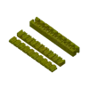
Decided to draw up this quick dovetail tolerance test to be used when needed for different purposes. 3mf file includes two of the same thing, thats by design. One should be printed vertically and one horizontally - turns out the fitment changes slightly depending how the modesl is printed This model helped me in:
- Choosing the tolerance to be used in CAD software for dovetail, depending on the use of the dovetail (something that would be removed and installed more often should have bigger gap vs something thats meant to be connected permanently )
- Helps choose tolerance base on printing position (horizontally vs vertically)
- Helps narrow down required fitment based on “how it fills” and removes the guess work out of equation.
P.S. Bambu Lab added dove tail cut in the receint uptdate. Based on my non-scientific experiments, Bambu Lab 0.10 mm dovetail cut is completely different from 0.10 mm in CAD (Fusion 360 in my case). Again, that was my experience.
Comment & Rating (2)
All

Print Profile
0.2mm layer, 3 walls, 15% infill
Probably even too much tests, a gap of 0.2 would have been fine also (and print faster). For my X1C I could move (without the hammer :)) from 0.10 to 0.07, rest is almost unusable.

0
Reply

Print Profile
0.2mm layer, 3 walls, 15% infill
0
Reply
No more
License
This work is licensed under a
Creative Commons AttributionRelated Models


© 2024 MakerWorld