Skip to content

Clearance tolerance test for 3D printing

Advertising
Advertising
?
Creation quality: 5.0/5 (1 vote)
Evaluation of members on the printability, utility, level of detail, etc.

  • 676 views
  • 3 downloads

License
3D design format
3MF, OBJ, and STL Folder details Close
  • clearence_test.3mf
  • clearence_test.obj
  • clearence_test.stl

Learn more about the formats

Publication date 2024-01-28 at 20:38
Design number 1745506

3D printer file info

3D model description

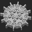
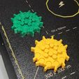
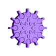
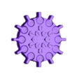
Tool to test your 3D printer clearance ranging from 0.02 to 0.24mm in both XY and Z direction.

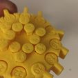
The numbers on the parts indicates hundredths of milimeters while the arrows indicates corresponding value. It was created to help with designing new parts, fine tuning the printer and finding out the right values for printing bearings. Both the levers and pegs stays in the model and do not fall out.

The tool consists of two sets of parts:

ROUND PARTS WITH LEVERS tests are dependent on extruder flow, filament characteristics (width), on the way your slicer works with model perimeters and on the inner/outer perimeter printing order.

After the print just try to move the levers. The biggest one (0.24) should move freely right after you remove the print and the smallest one (0.02mm) would be fused. The smallest number you can set in motion indicates the maximum clearence your setting allows. Some of them will need some force (you will hear loud snap) and then they will get unstuck while moving tightly.

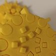
SQUARE PEGS in the middle are meant to test corners and swelling around them which are dependent on printer speed, linear advance, your toolhead innertia and layer height and width.

Push the pegs downards starting from the biggest one (the arrow indicates corresponding lever clearence) and find which one moves up and down freely. This tends to lead to poorer results than printing round parts as it moves across the layers and corners are always problematic on FDM printers.


If you want to dig deeper into those phenomenn I recommend Lost in Tech video or the Slic3r manual.

3D printing settings

IMPORTANT
By default slicers merge gaps smaller than certain value (usually 0.05mm) to compensate for faulty or errorneous models. You need to tweak this setting if you want to test the smaller limits.

  • no supports needed
  • elephant foot effect should be compensated by the design but it depends on your initial Z height, after geting the parts unstuck it shouldn't play a role
  • I do not recommend using brim as it will probably fuse the bottom together but if you encounter bed adhesion issue go for it
Advertising


Issue with this design? Report a problem.

Would you like to support Cults?

You like Cults and you want to help us continue the adventure independently? Please note that we are a small team of 3 people, therefore it is very simple to support us to maintain the activity and create future developments. Here are 4 solutions accessible to all:

  • ADVERTISING: Disable your banner blocker (AdBlock, …) and click on our banner ads.

  • AFFILIATION: Make your purchases online by clicking on our affiliate links here Amazon.

  • DONATE: If you want, you can make a donation via Ko-Fi πŸ’œ.

  • WORD OF MOUTH: Invite your friends to come, discover the platform and the magnificent 3D files shared by the community!


Sharing and downloading on Cults3D guarantees that designs remain in makers community hands! And not in the hands of the 3D printing or software giants who own the competing platforms and exploit the designs for their own commercial interests.

Cults3D is an independent, self-financed site that is not accountable to any investor or brand. Almost all of the site's revenues are paid back to the platform's makers. The content published on the site serves only the interests of its authors and not those of 3D printer brands who also wish to control the 3D modeling market.

100% secure payment by credit card, PayPal, Apple Pay, Google Pay, etc.
View all payment options.