Visual Upgrade for Ender 3 Pro - Powersupply PSU Relocation
Visual Upgrade for Ender 3 Pro - Powersupply PSU Relocation


Print Profile(0)
No Print Profile yet. Add one to earn points.
Description
Visual upgrade for Ender 3 Pro Printers
- Is not usable for Ender 3 and not tested on Ender 3 V2 (feel free to try it out for the V2)
Support me by covering a coffee to get/keep me going!
Venmo: @dannyjvj
SUMMARY:
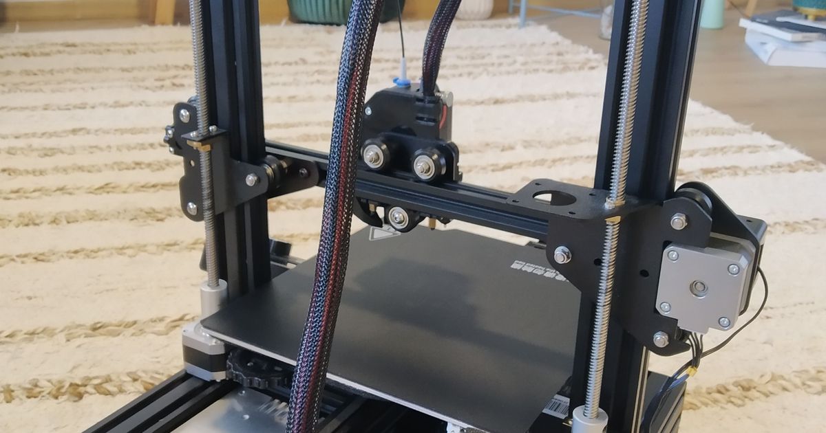
After upgrading my PSU fan to a much larger one, I recently needed to move my PSU for a dual z-axis upgrade. So, using the inspiration from many authors, I developed a combined model to suit my needs. That was to rise my printer up enough to have clearance for a thicker PSU (with my protruding fan upgrade). Models include the popular cable chains by johnnniewhiskey over on Thingiverse, a PSU mount for the Ender 3 Pro by Cancerix on Thingiverse, amazing riser feet by thrutheframe over on Thingiverse and also some inspiration by zoly15 here on Printables.
Find links to these models here:
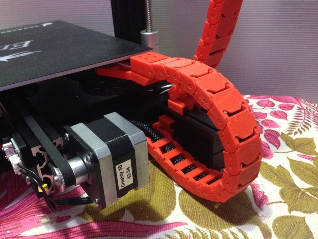
Cable Chains: https://www.thingiverse.com/thing:2920060
Ender 3 Pro PSU Relocation Mount: https://www.thingiverse.com/thing:5394166/files
Riser Feet: https://www.thingiverse.com/thing:4851027
Zoly15's Visual Upgrade for Ender 3: https://www.printables.com/model/154144-massive-visual-upgrade-for-ender-3-printers-powers
INSTRUCTIONS:
• Disconnect PSU, unscrew PSU from Z-axis profile and take off plastic cover.
• Unscrew power switch casing and disconnect three wires that connect PSU.
• Turn Y axis motor so that its connector faces front of the printer (only if it's not in this
position already).
• Turn Z axis motor or motors (if you have dual-Z), so that connectors faces opposite
each other.
• PSU correct position for install is fan on down, with contacts facing up and on left side
of printed (front view).
• Screw v-slot mount to PSU with original screws on side. Care about orientation up or
down
• Screw two rear brackets with M4 screws.
• Put PSU wires through the hole for power switch casing in bigger bracket.
• Place all cables into the slot on bigger bracket.
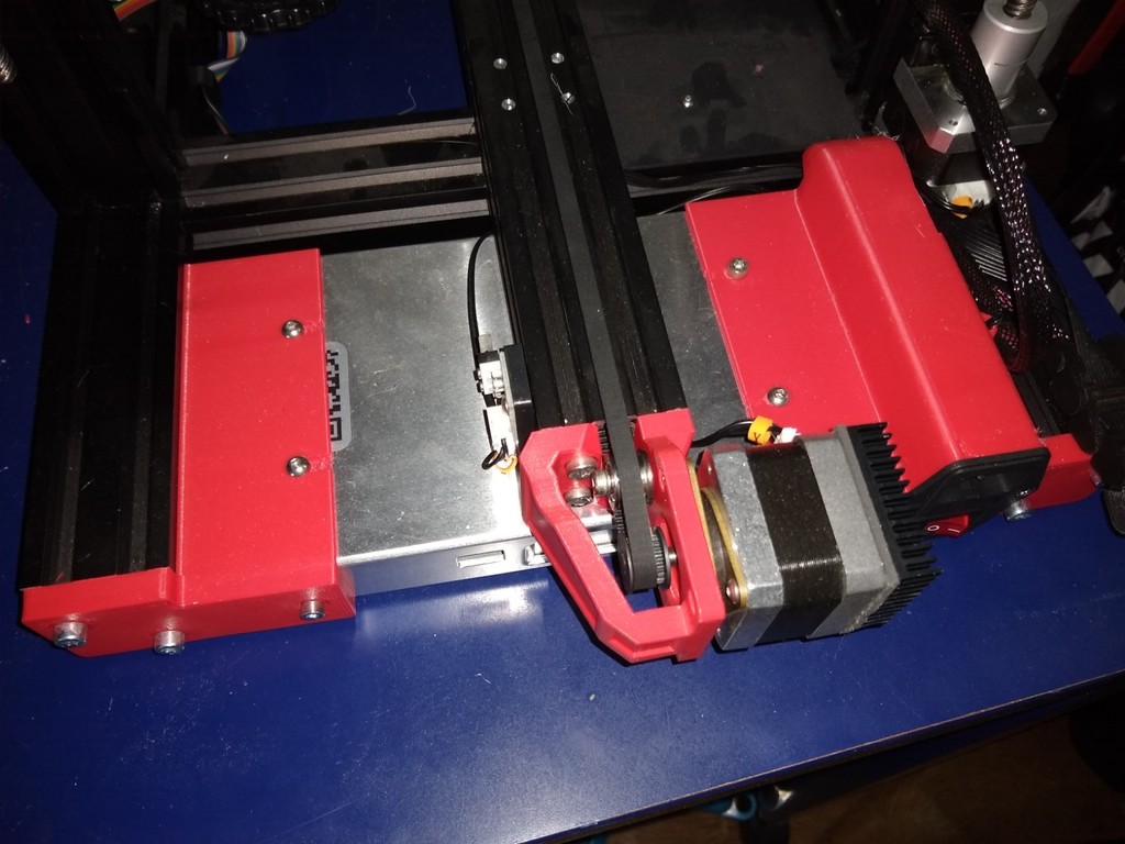
• Slide the PSU with mounted brackets under the hotbed into the v-slots.
• Mount the PSU by screwing the brackets to the printer by using four M5 screws.
• Connect wires to power switch.
• Screw power switch with original screws into their place.
• Install two front feet risers with using two M4 screws and two T-nuts.
• Shorten the original rubber pads for 2-3mm, by using the scissors, or knife (if needed).
• Stick the rubber pads to all four feet.
• Connect PSU cable and enjoy.
IMPORTANT NOTE:
Since the PSU is no longer connected to the frame, it is no longer grounded to the frame. This means you will need to ground your PSU to the frame using a small wire (see photos). I did this using the existing screw locations on the back right side bracket. I used telephone wire and secured it the same way your do an electrical socket on your wall (create a hook on the ends and fasten them down using the screws).
***Failure to do so may cause static buildup though-out your printer*** NOT GOOD!
Materials:
Screw list:
4x M5x10(or12, or16)
6xM4x8
2xM4x10
2xT-nut M4
Misc.
1x Wire of your choice for grounding purposes (and any mounting parts needed for this)
WARNINGS:
I AM NOT RESPONSIBLE FOR DAMAGES ON THE MACHINE.
DISCONNECT THE MACHINE FROM THE ELECTRICITY SOURCE BEFORE STARTING. I AM NOT RESPONSIBLE FOR INJURY BY ELECTRIC SHOCK. TAMPER AT YOUR OWN DISCRETION.
Comment & Rating (2)


This remix is based on