Hexagonal Vented Led Riser
Hexagonal Vented Led Riser


Print Profile(2)
Description
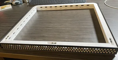
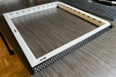
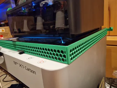
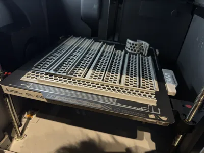
This is a very rigid led riser. Created for my needs and “style” :p
Features:
- Vented Leds (always active)
- Vented chamber (you can switch on/off by 4 slides)
- Sliding glass (with rails to make it slide smoother)
- Honeycomb dual color pattern (it helps to make the structure rigid, that's why it does not end to exactly half of the frame)
- Easy close, so that the glass does not stuck in front of the frame with the AMS weight on
- All piece are LABELED for an easy assembly
- Diffusers rails to add light diffuser (the covers are under development 02/01/24: Covers added)
- Lowest possible design
- Holes on the back to mount a DC/DC converter, esp32, or other hardware)
Caution when assembling the frame, there are actions you can't revert (like inserting the lock piece between two frames.
To assemble, put it upside down -letters visible-, arrange them on a surface where the left nearest corner is A, and counterclockwise b, c etc.
Insert the honeycomb in all bodies (the top must be higher than the frame body), and starting from A insert (and join) the vent slides*, stick the leds and insert the diffuser in the rail, then match the second frame piece (B) and TEMPORARILY insert half of the locker; stick other half side of the led strip, then insert the second diffuser into B. Proceed with other letters.
If you mount the diffuser also, you should start assembling sticking the led strip into E (wires hole), and mount from d→c→b→a→h→g→f)
Make you sure to clear ALL the rails (led, honeycomb frame and vents) before assembly, by sliding the pieces inside it, part to part.
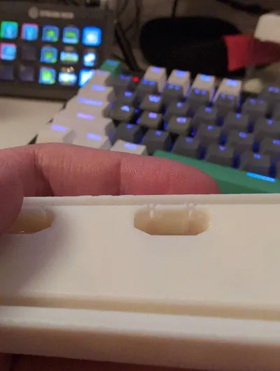
*Sliders are tight to a better seal, but they're very smooth after a couple of sliding (that's why you have to clear it before assembly sliding many time the pieces in). The back slide has a endstop who can give friction (slide F), you have to clear it inserting the endstop reversed directly from FSide (corner). the locks... yes, they are very tight
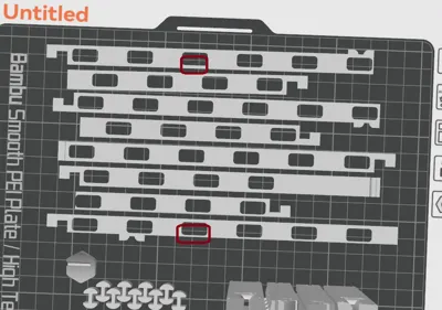
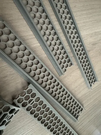
The harder pieces to print are the curved profiles, they're 0.5mm thicker for an easy print. PRINT @ 0.2mm/layer because of the overhangs. They have some small supports, break it once mounted on the frame.
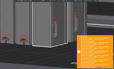
There are also some pre-designed supports in the frame itself, (in the corners) just break it with a screwdriver before mount.
edit: 02/01/2024
Diffusers added. Search in print profiles. You can insert it while assembling (better: If you mount a diffuser also, start assembling the led strip into E (wires hole), and mount from e to →d→c→b→a→h→g→f), or add later by printing ONLY the first layer (are 2 layers tot).
Because my frame was already assembled, i've opted for second choice. To better fix the covers (since they had no rails in my case because i've printed only the first layer), i've printed 2 more covers, cutted 1mm wide with scissors, and inserted into the rails to better hold the covers. I've tried to slide it into an old test frame (diffuser printed in 2 layers), and it goes ok.
Comment & Rating (22)