Simracing VoCore 6.8" DDU
Simracing VoCore 6.8" DDU


Print Profile(1)

Description
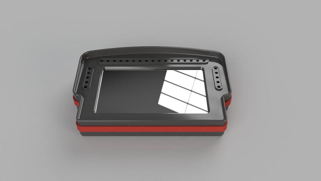
I found the 5" displays a little too small for my taste and wanted to go with the 6.8" display. I didn't find too many existing models for this so decided to design my own taking inspiration from what was out there. My goal was to make a very high quality model with ease of printing/assembly in mind. In its current state you'll have 2 USB outputs for this DDU. In the future I'd like to create a custom PCB to get that down to a single USB output (please contact me if you'd like to help with that development as it's a bit outside my wheelhouse).
The mounting bracket is designed for a Simagic Alpha Mini. I can make new brackets for other wheelbases if you send me dimensions. The bracket is designed to allow you to slide the display very low as I wanted it just above the steering shaft but you can slide it up high as well if that fits your needs.
The display and LEDs can be controlled by SimHub or similar software. I highly recommend the Lovely Dashboard and Daniel Newman Racing LED Profiles (no 5-20-5 profiles at the time of this writing but he said he'll be making one in time). Please support these projects if you find their work helpful (I have no doubt you will!).
Bill of Materials:
- M3 x D4.2 x L6.0 Thread Inserts (11)
- M3 x 8mm Countersunk Head Screws (4 - Enclosure)
- M3 x 8mm Button Head Screws (3 - Arduino Mount)
- M3 x 8mm Thumb Screws (4 - DDU Mount)
- VoCore 6.8" Display
- Arduino Nano
- WS2812B Individually Addressable Led Strip (1m 144 IP30)
- Micro USB Cable
- Mini USB Cable
- 24 AWG Wire
- 3M Double Sided Tape
- Faux Carbon Fiber Build Plate (optional)
- M8 x 12mm button head screws (2 - may be different for your wheelbase)
Printing:
Optional: I used the faux carbon fiber plate to give that look to the front and back of the enclosure.
Material: PLA or better for housing, TPU for display gasket (optional)
Layer height: 0.2mm
Wall loops: 4
Top shell layers: 4
Bottom shell layers: 4
Infill: 60%
Infill pattern: Gyroid
Supports: only needed for the countersunk holes on the mounting bracket and wire passthroughs on the side of the front enclosure


Assembly:
- Melt the threaded inserts (11) into back enclosure using a soldering iron
- Set temperature to melting temperature of material used
- Make sure inserts are flush with outer surface


- Cut LED strip into 3 sections (Tip: these LEDs are very close together and can make soldering the center connection difficult. You can sacrifice an LED when cutting and leave a larger portion of the connection to solder onto to make things easier. It's doable without doing this though.)
- 2 x 5 LED strips
- 1 x 20 LED strip
- Solder the LED strips together using 24 AWG wire
- ~36mm for outer wires
- ~33mm for middle wires
- ~30mm for inner wires
- Make sure the arrow on the PCBs are all pointing the correct direction (away from Arduino)
- Solder Arduino Nano to LED strip
- ~60mm wires
- Solder directly to the Arduino, no pins needed (there are cutouts on the Arduino mount to allow the wires to poke through the back)
- Use VIN (red wire), GND (blue wire), and D6 (white wire)
- Remove adhesive backing from LED strips and place them on the platforms
- Start with the 20 LED strip
- Notice that there is an alignment arrow on each platform for the center point of the strip
- Start at the center and slowly work your way out
- Once perfectly aligned, repeat the process for each 5 LED strip
- Screw down Arduino cover using button head M3 x 8mm screws

- Test fit the front enclosure to make sure LEDs are aligned with holes, adjust as needed then remove front of enclosure (be careful sliding over the Arduino USB port)
- Use double sided tape to attach the ribbon cable seat to the back of the VoCore display then use another piece of tape to attach the ribbon cable to the seat as shown in the picture

- Thread the USB cable for the VoCore display through the right port on the front enclosure and press it into the cable clamp to prevent accidental pulling of cable
- Leave about 140mm of cable to plug into the display

- Leave about 140mm of cable to plug into the display
- Carefully plug in the display and rest it onto the mounts (ensure wires are out of the way and not being pinched/pulled)

- Optional: glue the TPU gasket to the inner face of the front enclosure (I didn't end up using this and everything seems to stay in place nicely)
- Carefully slide the front enclosure over the back enclosure and secure using M3 x 8mm countersunk screws (4)

- Attach mounting bracket using 4 M3 x 8mm thumb screws (don't quite fully tighten these yet so that you can fine tune the positioning once it's mounted to the wheelbase)

- Attach the mounting bracket to the wheelbase using M8 x 12mm button head screws (may be different for your wheelbase)
- Position DDU at desired height and tighten thumb screws
SimHub Setup:
The display should be recognized right away by Simhub. You can simply navigate to the device tab and load the dashboard of your choice and adjust the display to your liking. Again, I highly recommend the Lovely Dashboard. Note that you'll need to flip the display.

For the LEDs, you'll need to flash the Arduino using the provided tool:


Make sure you select the correct COM before flashing. If you don't see your COM listed you likely need to install the drivers.
After it's flashed, you'll need to configure the LED profile to your desired behavior on the RGB LEDs tab. This is fairly straightforward but you can definitely get very detailed in your configuration. Definitely check out Daniel Newman Racing LED Profiles to see how crazy/awesome this can get.
Have fun and I welcome feedback!
Edit 1: Added alternate faceplate with rectangular LED openings instead of round.