HCR System (Highly Configurable Riser)
HCR System (Highly Configurable Riser)


Print Profile(4)


Description
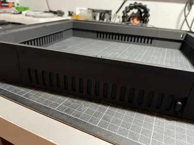
May I present the HCR System (Highly Configurable Riser). This is the product of over 100 hours development and too many rolls of filament in protoypes to mention!
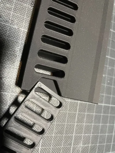
You can print completely vented, partially vented and place them on whichever sides you choose or without vents at all. The pieces are interchangeable. You can print with or without the LED bar as well.
The printer profiles I have uploaded are for a HCR System with 4 vented sides and the optional LED addon bar with the LED passthrough on the rear left side and also with the TPU shim. If this is your desired configuration then you can simply print these plates, otherwise you can pick and choose using the below guide.
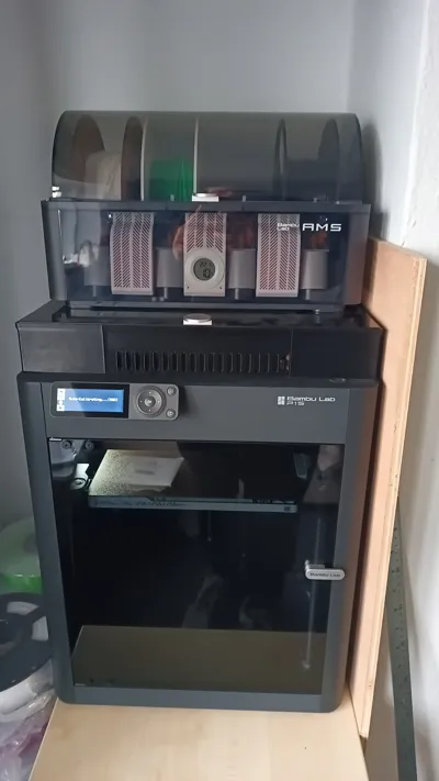
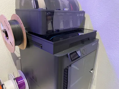
The LED strip can run straight from a power supply or as I have it here using the excellent BL LED box from Dutch Developer. It turns the lights off during lidar operations and goes green at the end of a print and red if there is an error, and yes, there is a rainbow mode!
https://www.etsy.com/listing/1452127613/bl-led-controller
https://dutchdevelop.com
PRINTING:
TIPS:
Printed with PLA - but suggest PETG or higher depending on materials you print.
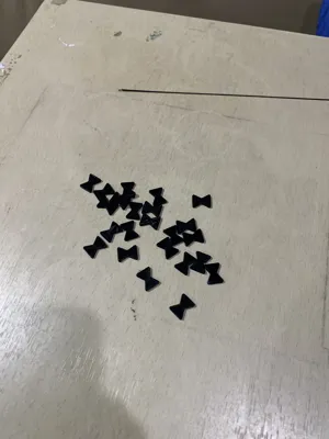
Print Bowties on a plate of their own in the middle of the plate without brims.
If you are printing with a different slicer software consider using Bambu Studio. I had far fewer part corner lifts than with Orca for example on default settings.
You can print with 5% sparse infill but 10% is better and 15% is best
If you have problems with bed adhesion with the large parts consider turning off the aux and chamber fans or printing with a brim or slow the inner and outer walls down to 75.
I have numbered all the pieces to make it easy to know what to print and how many of each to print. This will obviously change depending on the configuration you choose but should be fairly simple to follow.
1. RISER CENTRE
You will need to print a total of 4 of these. Choose any combination of vented and no vents to suit your needs.
2. RISER SLIDER
For each vented centre (part 1) you chose you will need a slider.
3. RISER FRONT LEFT CORNER
You will need to print 1 of these.
4. RISER FRONT RIGHT CORNER
You will need to print 1 of these.
5 + 6. RISER REAR LEFT CORNER / RISER REAR RIGHT CORNER
You will need one each of these. If you are going to use the LED bar, print the holed piece on whichever side you want the LED strip to be fed through, print a no hole for the other side. Print 2 x no hole if you do not want to use the LED bar.
With steps 1-6 you now have the entire frame for the riser.
Next is the optional LED bar.
7. LED CENTRE
You will need to print 4 of these.
8. LED FRONT LEFT CORNER
You will need to print 1 of these.
9. LED FRONT RIGHT CORNER
You will need to print 1 of these.
10 + 11. LED REAR LEFT CORNER / LED REAR RIGHT CORNER
You will need one each of these. Print the holed piece on whichever side you want the LED strip to be fed through, print a no hole for the other side. Please make sure you print the same side hole as the riser!
With steps 7-11 you now have the entire LED bar.
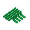
12. BOWTIE TOLERANCE
Now print the three tolerance files and snap fit some parts together. You want the fit to be snug but not overly difficult to clip together.
13, BOWTIES
Using the correct tolerance from part 12, print 16 bowties for the riser alone and 8 more for a total of 24 if you are also using the LED bar.
Finally the TPU shim to sit between the plastic and the original glass top of the X1 Carbon to avoid scratches.
14 + 15 + 16 + 17. TPU SHIM
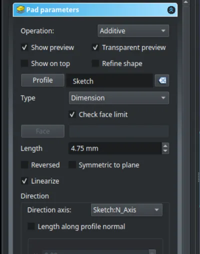
Print 1 of each. SLOWLY! TPU is notoriously difficult on larger objects - see the print profile having all the speeds lowered to 60mm/s and the travel speed set to 400 and the acceleration set to 5000.
That takes care of all the printed parts.
ASSEMBLY:
TIPS:
If using the vents - make sure slider is inserted before assembling frame. Gently slide it all the way in and out to ensure it moves freely, but should have a small amount of friction so as to not rattle when the printer is in use.
Make sure LED bar is resting on the ledge of the frame before fixing with bowtie.
RISER:
Insert the sliders into the vented pieces and place in a square with the slider knobs facing outwards.
Place the front left, front right, rear left and right pieces in their corresponding positions. Make sure the longer edge of each of the corner pieces points towards the middle back or front of the printer.
Attach the bowties around the top of the riser, turn over and repeat on the bottom.
LED BAR:
Firstly feed the correct amount of LED strip through from the hole in the rear corner piece.
Now feed the LED strip through the LED bar corner piece with the hole and use a bowtie to clip the corner piece to the riser.
Now slide the LED's into the LED centre part and then attach to the riser using a bowtie.
Repeat for the remaining corners and centres until you have all the pieces in place.
Peel back the adhesive from the end of the LED strip and stick to the inside of the corner near to the hole.
TPU SHIM:
Assemble the four parts into a square and lay on top of the riser. You can of course double sided tape or hot glue the shim down if you want it to stay in place.
Congratulations. You now have a completed HCR System.
Please feel free to share your builds, comments and suggestions,
REVISION HISTORY:
V1 - 27/Dec/2023
Initial Design
V2 - 31/Dec/2023
Changed all fixings to standard Bowties
V3 - 3/Jan/2024
Added LED housing to inside of main frame.
Vertical mounted space for LED bar added
V4 - 6/Jan/2024
Vertical space for LED's increased.
Corners rounded for LED track
V5 - 8/Jan/2024
More holes added to hot air vents
Reduced travel required to open and close vents
Slider handle moved to right so as not to sit behind the touchscreen of X1C
LED bar moved to optional separate part
V5.1 - 11/Jan/2024
Increased thickness of slider piece
Redesigned slider slot on centre piece
Lip added to main frame for LED bar to rest on
V5.2 - 16/Jan/2024
Height of slider knob reduced
LED bar changed orientation to vertical with downward facing holes
V5.3 - 17/Jan/2024
Adjusted clips to hold LED's in
V5.4 - 21/Jan/2024
Reduced bowtie depth from 5mm to 2mm for easier fitting and removal
V5.5 - 22/Jan/2024
Complete redesign of LED bar to 45 degree angled down
V5.6 - 27/Jan/2024
Added holes to bottom of LED corner pieces to minimize dark spots on the corners of the build plate
V5.7 - 27/Jan/2024
Initial release on Makerworld
V5.8 - 31/Jan/2024
Updated the riser 3mf file to use the correct larger holes for the thicker slider pieces. Thanks go to @fanatikz for noticing.
Comment & Rating (22)