P1S Vented LED Riser
P1S Vented LED Riser


Print Profile(2)


Description
UPDATE SEE TEXT BELOW:
There are many risers on Makerworld for the P1S, P1P and X1C. Many are very big and full of features I do not have any need for.
I only need:
-a place to mount more led lighting
-create permanent ventilation near the top
-raise the glass top for more clearance for the cable and ptfe tube. (it rubs the glass plate on some prints and makes rattling noises)
-create a stiff connection between the riser and the main body of the printer
-create a look as if it belongs on the printer
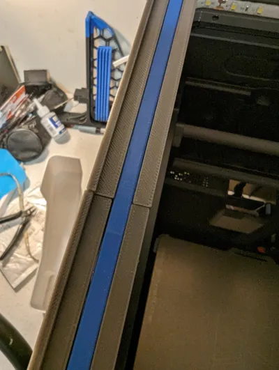
I created a fit with small tolerances. I designed the fit with the main body in such a way I can fit electrical tape on all sides to clamp the riser and cushion fibrations. Result: solid connection, no fibrations. I recalibrated so the printer can learn the new characteristics with the added mass and raised AMS.
Vents in both sides are open in the “closed” position. I mostly print PLA, so I want heat te escape in most of the times. I can close the vents by pulling the left and right slider in the “open” position.
UPDATE and WARNING:
Darren.Meier commented on using the original small usb connection to connect the much longer 5V LED strip. He warned the original usb connection is rated for 0.3A and the long LED strip is likely to draw up to 2A. This is not a good thing for the electrical system of the printer.
Solution:
- Attach the original LED strip to the original connection (or do nothing if you haven't changed it).
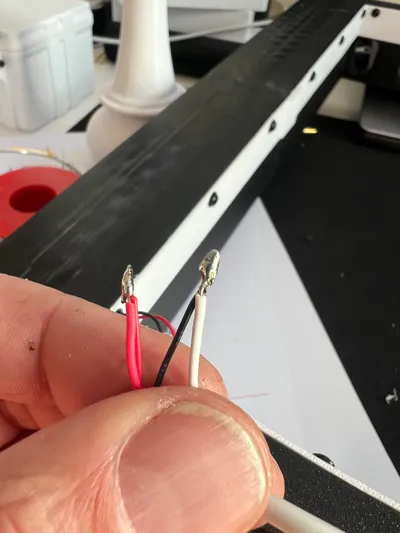
- Cut of the connector of the long led strip and attach a standaard USB A connector. I used an old cable I no longer use.
- Solder the + from the LED strip (it is often printed on the strip itself) to the red wire from the USB A.
- Check with a poweradaptor of you phone if the LED's go on. If not switch the cables. (My chinese LED's were colorcoded but the wrong way…)
- Connect the USB A to the external power USB. This is located on the right side of the same printboard as the small connector. You can easily cable manage using electrical tape.
Result:
- Original LED reacts as normal
- Vented Riser LEDs are on when the printer is on.
OLD text no longer valid: LED strip uses the original usb connection so it operates exactly like the default lighting. It is a replacement of the default lighting.
Assembly:
a) Print all plates.
b) Glue the riser parts together, with the slides already in place. Once glued the slides cannot be inserted. I used vasiline to lubricate the slides a bit. They need to have a tight fit, to prevent rattling. I used a picture frame strapclamp and squares to glue all 4 parts at once on a flat table.
c) I bought on AliExpress some simple LED strips (photo included) that can connect to the EXTERNAL POWER USB of the printer (photo included) after soldering a regular USB A connector on it. Stick the LED strip in place. Start at the left front corner with the wired side. Follow arround, make sure to press firmly into the corners. Cut to length when you arrive at the front left corner again.
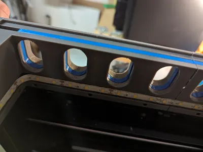
d) Attach the LED Diffusers. You need 4x6 M3x16 screws and heat inserts. The LED Diffusers are modelled without tolerances, so some light sanding on the connecting ends is needed. (5 minutes sanding at most for the perfect fit)
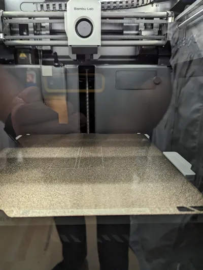
e) Remove the glass plate from the printer. On the riser, drill out some relieve for the screws of the glass plate knob. Is used M3 whashers and a soldering iron to sink them in approximately 2 mm. Stick one layer of (black) electrical tape (10cm) on the place the glass plate rests on and against each side. This electrical tape forms a press fit with the riser. Not rattling, even on hefty print jobs.
f) rerun the calibration of the printer
Comment & Rating (9)