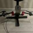
I’ve tried to summarize all of the work I’ve done with a reasonably efficient description of each step and some instructions. Any feedback or suggestions would be really appreciated. I estimate the handlebars are about 80% where I want them to be.
I’ve still got to work on:
The clean look of the whole system – the wires, electronics box and general vibe of the aluminium
The mounting of the linear potentiometer – I messed up the measurements (now adjusted for their correct width in the file)
The handlebar mounts even at their tightest still allow the handlebars to twist a bit with some pressure.
Dependencies:
https://cults3d.com/en/3d-model/game/50-8mm-to-70mm-bolt-pattern-adapter-for-steering-wheel
All Files and Progress images available here:
https://drive.google.com/file/d/1YkU08pbUXcodJXZ_9UWcvA9zXV3Dh5Pr/view?usp=drive_link
I’ve not been able to add photos to my posts yet so all have been uploaded and labelled in the above link. I’ll likely upload the code and files to some other sites as well to make them more easily accessible.
Required Equipment Shopping List:
Nuts & Screws
4 x 4mm x 7mm nuts bolts
1x 5mm x 7mm nuts bolts for lbracket
4x 3mm in design. Need 2
2x bike brake mounting nuts bolts included 5.6mm diameter
6x quick release 1 bolts included
2x bolts handlebar mount included
1x washer diameter core 1.4mm<4mm
40rmb total.
Bike Cable crimp tie off - 7rmb
L bracket 20x20x16 -3rmb
KTRC linear pot with spring 20mm travel -85rmb
2x 1k resistors -2rmb
Arduino pro micro 25rmb
XF- Hx711 with 80hz mod 10rmb
1.25mm cables and connections with female/male connectors 6pin, 5pin,4pin,3pin -10rmb
Motorbike box stl 3d printed v0.6 -10rmb
Motorbike base dxf CNC on 5mm 6061 aluminium v0.6 - 80rmb
3 part handlebars. -190rmb
22mm diameter:
2x handlebar mounts -17rmb
1 throttle with switch and additional handlebar grip -30rmb
5x switch (optional) -35rmb
Small load cell -5rmb
1x disc brake, cable and lever -68rmb
1x brake cable and lever -14rmb
1x Momo quick release v1 or alternative mount. -105rmb
Approximately 736rmb worth of things
$105 usd in parts.
Other optional: Multimeter for testing.
High quality usb cable
Files for CNC and 3D Printing:
Mounting board for all hardware as DMG
https://drive.google.com/file/d/1YkU08pbUXcodJXZ_9UWcvA9zXV3Dh5Pr/view?usp=drive_link
Box for Electronics as STL
https://drive.google.com/file/d/1gWj0syKul5UYiLviwSdprBLSwJ0wLE96/view?usp=drive_link
E-Throttle:
Cut off plugs that come with standard E-Throttle but take note of which ones are for the switch (2 cables) and which are for the throttle potentiometer (3 or 4)
Connect to a 5 pin cable similar to below after testing for each cable’s purpose.
5 pin - Throttle - gnd vcc and 1, Switch - gnd and 1
Brake System:
Cheap cable disc brakes are suitable, you’ll have to file down the brake pads so that the small load cell can fit between them similar to the progress photos shown in the google drive link after using some hot glue to help keep everything mostly in place.
Make sure to protect the cables that are connected to the load cell.
Connect the single load cell to the 4 pin plug. Only connect 3 cables as the 4th cable will be used on the Arduino board with the two additional 1k resistors.
4 pin - Load Cell- E+ E- (A+) A-
Clutch:
Thread the cable with a washer through the L-bracket and connect it to the KTRC potentiometer and secure with the cable crimp through the pot hole.
This can then be mounted on the right side of the mounting board on the back side
Test or use the circuit diagram to explain which wires to wire together. Some pots have an additional GND shield that can be ignored.
3 pin - Clutch - gnd vcc and 1
Button pads:
Combine the ground cables, one for each button.
6 pin - gnd & 5 separate buttons
Electronics box:
Use Arduino IDE to connect your Pro Micro and install the sketch listed in the google drive - https://drive.google.com/file/d/1hwLeQtzYrn4penaZjkBjBFWK_BTkbd_3/view?usp=drive_link
Add paper as insulator to bottom of the box.
Hot glue the vcc and gnd rail connections.
Right side of the box should hold the 5-pin and 3-pin plugs
Left side of the box should hold the 6-pin and 4-pin plugs
Mount the box on the front or back of the mounting board
Software setup:
Most straightforward way to setup your software is using x360ce found at
https://github.com/x360ce/x360ce/releases/download/4.17.0.0/x360ce.zip
There is no forcefeedback so you can experiment with another program called XOutput but this program doesn’t seem to recognise the brake system currently.
In Steam - MUST disable mouse control in controllers everywhere otherwise it interferes with the axis
The “Steam Companion App” also interferes. make sure games in x360ce are using Output 1.4 dll under the game ‘options’. No ffb yet but it doesn’t crash.
You will need to calibrate the controls in the “windows usb controller manager”-> settings-> calibrate
Possible Future steps:
Replace Handlebar Mounts with something more secure to prevent rotation?
Mount electronics on the back of the board?
Set up the gear with handlebars above the mount? Is possible but haven’t tested it
Design PCB for plugs to be mounted to? Beginnings in KiCad https://drive.google.com/file/d/1DSfTuVqLF1BBWgbzZSdhfAKoBDwNB8Ap/view?usp=drive_link
Solve x360ce ffb with Simagic software
Solve rotation amount with Simagic software – currently 90degrees
Better channelling of cables to keep everything hidden?
Gear change and rear brake attachments made on the sides of the rig from pedals?

/https://fbi.cults3d.com/uploaders/32222799/illustration-file/4e6ee01a-832d-4e39-9b56-7ad96bc6b46a/IMG_8821-small.jpg)


