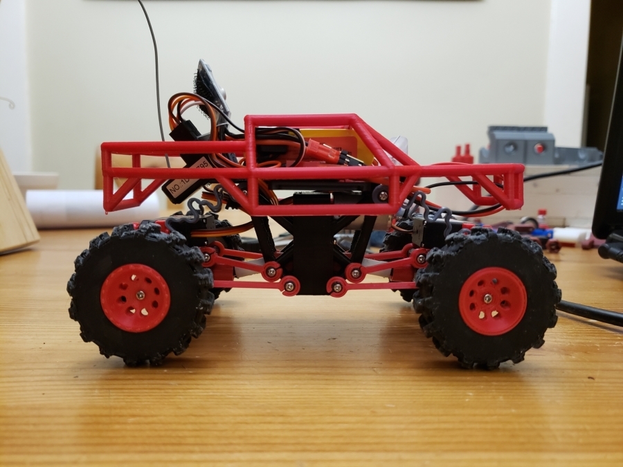
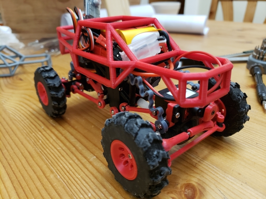
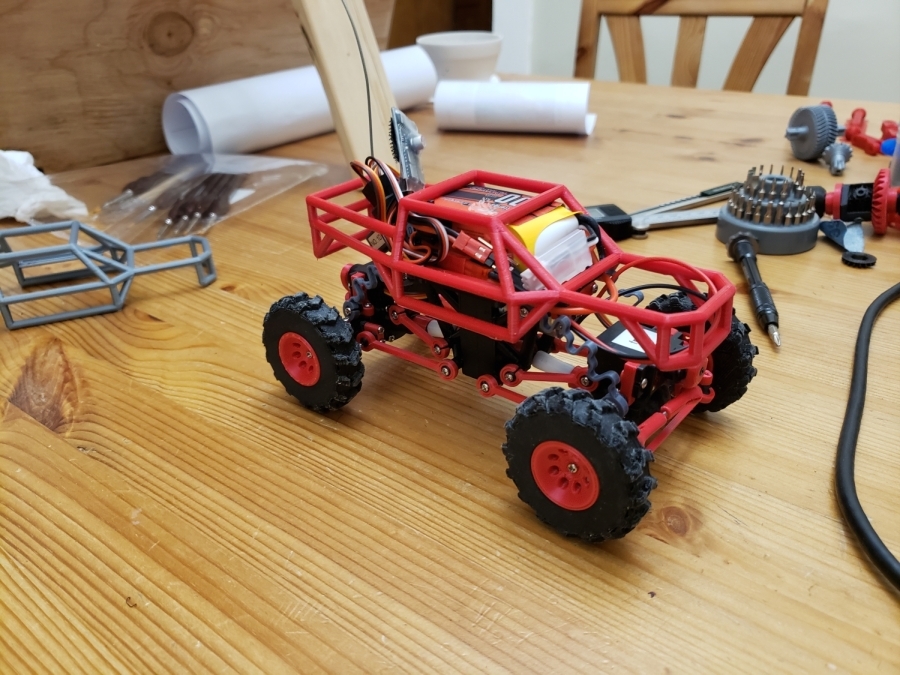
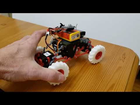
1/24 RC rock crawler, with new gearbox
Assembly manual along with bill of material (BOM) now available at https://github.com/tremrej/RCRockCrawler/tree/master#rockcrawler. That site also include all the 3d printed parts from the original design. All you need is there.
Version 1.1 (Feb 7, 2022):
- I updated the frameFront_v2.stl. The original one was a bit tight for the motor.
Version 1.2 (Feb 8, 2022):
- New frame front/back with proper hole for screw
- New gearbox front/back with proper hole for screw
Version 1.3 (Feb 13, 2022):
- New wheel, 26.5 mm. Fit better with the tire I bought. The original wheel were too small.
- New, stiffer, shock (shock_46mm_1.0_5.45_off.stl). It prevent the front axel to twist when climbing a steep hill.
- New motor holder for brushless Rocket 1410.
Version 1.4 (March 9, 2022):
- Updated the plate with a slot for the screws. The holes in the previous version were off a little bit.
Version 1.5 (March14, 2022)
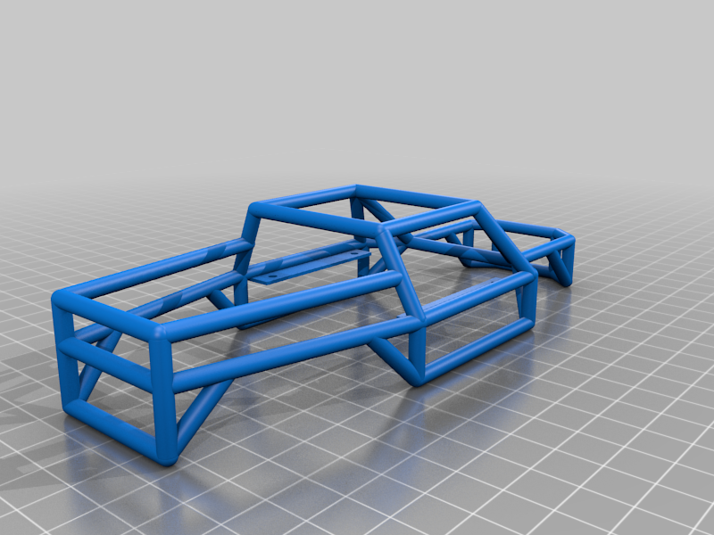
- New body (body_v3.stl), easy to print: Require support only for the screw plate. See image.
Update, Feb 8, 2022:
- I tried this motor: https://outofdarts.com/collections/motors-2019/products/meishel-2-0-130-2s-motor-for-nerf-blasters. I like it. Much more torque than a cheap motor 130. So far this is the best motor I've tried. I'll post a video whenever I find the time to do so...
- I just realized you need to finish the hole for the screws on both part of the frame. Use a 1.8mm drill (1/16 inch). I'll correct that eventuallly. This is fixed in version 1.2.
Update, Feb 13, 2022:
- I've tested a brusless motor, Rocket 1410, version 2500KV. The only required mod is a motor holder (back plate) which has a little notch to prevent the motor from twisting. File motorHolder1410.stl. I love this motor. It provides better control at low speed, more realistic. But it's more expansive (40 us$ with controller).
- I've create a new video where you see there three motors in action. But it's not a face to face comparaison. Sorry.
- I also create a video showing the assembly of the new gearbox.
Update, March 9, 2022:
- I tested this motor: https://www.aliexpress.com/item/32878376079.html (not affiliated). It's much cheaper than the Rocket 1410. It has enough tork and low speed. I actually prefer this motor to the Rocket 1410, mainly because it has lower speed, which provide more precision to climb obstacles.
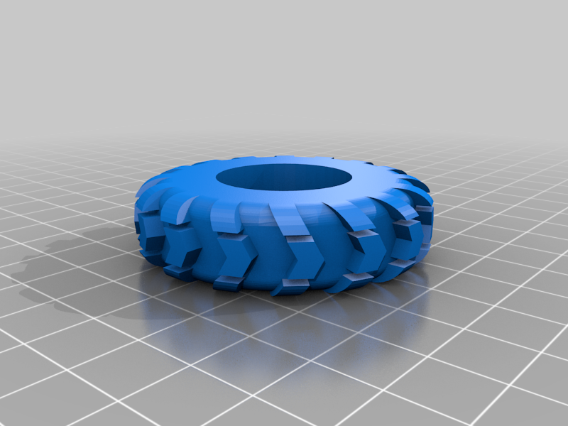
- I also printed the tire using TPE85A. The grip is pretty good. Not as good as commercial tires but pretty close. Good enough to climb a piece of wood at 45%. I got mine from https://3dprintingcanada.com/collections/tpe/products/black-1-75mm-tpe-filament-0-5-kg (not affiliated).
Video:
- In action: https://youtu.be/3EBpf9YP5C4
- Showing the shock: https://youtu.be/YSYngEb9dG8
- Gearbox assembly: https://youtu.be/KAkp_eB5qdQ
- TPE tires and new motor: coming soon.
List of part to print: https://drive.google.com/file/d/1gyE06sXocmIVC6YyiQa47B3-vM9KMiIj/view?usp=sharing
New gearbox
This machine is a little gem. I like that it is 100% 3D printed (beside screws and bearing). There are some aspect that I felt could benefit from a revision. The main one being the gearbox. The original one has a ratio of 1:5.6. This is too fast. The machine feel like a drift car rather than a crawler.
So I took it on me to design a new one. And I did. It's a big improvement, at least from my point of view. The new ratio is 1:15.9, i.e. three time slower, triple the torque. I'm currently running it with a
cheap motor 130 and the improvement is impressive.
The design of the new gearbox uses the same geometry at the old one such that the rest of the vehicule uses the same original part, except of the center drive shaft which I had to make 1.5 mm longer.
A bigger ratio was the main objective for the new gearbox. Another objective was to make it easier to print. To achieve that I split the gearbox in 4 pieces: 2 pieces for the gearbox and 2 pieces for
the frame. The end result makes the car, specifically the wheel base, about 2 mm longer.
The drawback of the new gearbox is a higher center of gravity. The plateform is higher by almost 10 mm.
Technical info: the gear of the original and new gearbox uses a module of 0.5, i.e. the pitch is 3.1416/2 mm per teeth.
I design the new gearbox using Openscad. Let me know if you are interested by the design file. I can make them available. They need a bit of cleanup before I do so.
If you print the gear for the motor (gearMotor.stl) it's a good idea to use for glue (like cyanoacrylate, aka crazy glue). Just press fit is not good enough when the motor get hot. If you buy the motor with the
gear already installed make sure the gear is a 8 teeth, module 0.5. This is pretty common for a motor 130. You can buy the gear for the motor in brass. It will last longer than printed in PLA.
Other changes (improvements)
- I redesign the connnecting rod for one main reason: the original one were difficult to install and remove. The new one are much easier to install and remove, and easier to print as well.
- I suggest to print the Center_Drive_Shaft_-P2.STL in TPU for two reason: it provide a bit of flexibility to absorbe the torque of the gearbox going to the axel and it make the Center_Drive_Shaft-_P1.STL much easier to insert in part 2.
- I redesign the shock. I had no real success at printing the original one. So I designed a new shock which is much simpler to print and they work pretty well. The only drawback is that it doesn't look like real shock. You can print them in PLA or PETG, PETG is a bit better: it doesn't "fatigue" as much as PLA. And PLA is not as flexible as PETG.
- I designed a longer set of hub and drive cup which are 1.5 mm longer. This is good for wider tires. It prevent the tire from touching the connecting rods.
- I also adapted the design of a tires to be printed in TPU. There are good but the grip is not that great: the TPU is not flexible enough. The original design of the tires is from https://www.thingiverse.com/thing:437669.
Observation
There are some discrepancies between the model assemble in the original video and the stl files provided with the original model. I noticed three differences:
- No bearing at the output of the axel. And there is no need to. It works perfectly fine without.
- The ball joint of the lower part of the shock is on the servo holder instead of being on Axle_Case_p4.STL.
- The design of the shock is also different. See the section above where I propose a different type of shock.
### Part to pay attention
- There is a recess in the gear G34_P14_p1.STL. This recess is important so that the gear doesn't touch the outer ring of the bearing. I've had good result by using a raft when printing that piece.
- The battery to use are not AAA. They are 10440 which are lithium-ion with a voltage of 3.7 volts each. Two batteries in series give you 7.4 volts. You need that in order for the ESC to work properly and for the motor to provide enough power. I use a 2S lipo battery which provide the same voltage.
### Bill of material
- The original BOM as shown in the description of the YouTube video Part 2, of the original model is missing two elements:
- A 2mm smooth rod. You'll need a piece of about 13 mm to insert in M0_5_19T_11T.STL.
- A threaded rod M2. You'll need two pieces of about 10 mm to connect two 5.5_Link_Closed_35mm_C.STL together.
Recommendation
- I used grease (with PTFE) on all the gears and the all the hubs. It help to reduce the wear and it improve the power transfer to the wheels.
Next step
- I plan to try different motor, hoping to find one with higher tocque and less speed. I even ordered a brushless motor. I know, this is much more expensive. Well: That's how I like this truck. I'll update this post if I get good result with these new motors.
- I'd like to design a new body, easier to print. I don't know if I have to skill to do that.
:format(webp)/https://fbi.cults3d.com/uploaders/15215294/illustration-file/df60603a-fbcb-4d8e-ba02-7baf34baecbf/rcRockSide.jpg)


/https://preview3d-images.cults3d.com/c68ts4sogud9tlu2vsjl2kskl740)
/https://preview3d-images.cults3d.com/2qv2noll1o3ts1a6b8c94d4u9g4v)
/https://preview3d-images.cults3d.com/ujdfma508iedbu923k43tsxevu1y)
/https://preview3d-images.cults3d.com/howminxc4fmfbve1l2evg3xjnks1)
/https://preview3d-images.cults3d.com/u219huzvxuj214wwrmam4skicxcq)
/https://preview3d-images.cults3d.com/xiqbeherkiaw0d395kryjru0fsk9)
/https://preview3d-images.cults3d.com/7s0my7djwfwmj2svna9fuudbeyym)
/https://preview3d-images.cults3d.com/fv6hl0rao7lhqeqobww6a0uwsh4q)
/https://preview3d-images.cults3d.com/tm3pciuyubwkvvv6i97m3y2yao09)
/https://preview3d-images.cults3d.com/5z9s190h0c1xaa67k5rd1hoef2qu)
/https://preview3d-images.cults3d.com/h46k1lv1yp6l5olzj2nod3hd8fbi)
/https://preview3d-images.cults3d.com/h4grgpphicofh60veahrxxn6k55p)
/https://preview3d-images.cults3d.com/75u60o8v2kycvoecwrpgrc1xi7jn)
/https://preview3d-images.cults3d.com/4dnzob302msht3fgt4m7b2gtamvg)
/https://preview3d-images.cults3d.com/7lzz9vfnq8ah8t1h0pfescklq34j)
/https://preview3d-images.cults3d.com/liddg5rk52shiw8pc3cwcm3ega89)
/https://preview3d-images.cults3d.com/bddjmyncmmnv3rlplsubmyrh2zv7)
/https://preview3d-images.cults3d.com/xngsfd6bjqco7seqqd3u5x3sbgjx)


