Xinkebot Orca 3 bed cables mod/fix

Description
PDFIntroduction:
Some time ago I made a terrible mistake and bought an Orca 3 IDEX 3d printer from not much known brand Xinkebot. On paper it had pretty nice specifications, and looked as interesting and well thought design. Which indeed was true in that case.
What killed that product though, was TERRIBLE quality of assembly, total lack of quality control, and overall awful craftsmanship of factory. Also few design choices revealed to be just bad and lacking long-term testing if they are reliable enough.
Result was that my machine suffered from couple of major hardware failures after mere 20-25 hours of work. Over recent year I addressed majority of its flaws, tested invented solutions, and now can share them to everyone who was unlucky to get those machines.
Solution1:
Heated Bed ribbon cable
Original Xinkebot solution utilize a 10 pin ribbon cable laid in two plastic rails attached to the upper cover of the base of machine and underside of bed structure. They are mounted that they slide through and into each other, with ribbon cable being dragged and bent back and forth inside when bed does its motions along Y axis.
Issue is - ribbon cable is forced to bend with very tight angle, and additionally - prone to grind over sides of plastic rails it is laid within. Right outer cables of the ribbon are transferring termistor signal, so they are first to fail when grinding back and forth against plastic rubber finally is grind to dust and wiring gets damaged, triggering machine to failstop mid work. Even if Your unit is assembled good enough, that ribbon cable is not touching rough plastic rails during its movement, its very likely that it fails soon anyway because of wear from very narrow angle it is forced to work.
Instead of rails and ribbon cable, I decided to use plastic drag chain laid horizontally, housing all 10 cables separately. It fits tight space under Orca bed nicely and prevents cables from overly early wear and fail.
Required hardware:
- Plastic drag chain 15x18mm, around 48cm length
- 4x M3 6mm flat-head screw
- 2x M3 8mm flat-head screw
- 6x M3 nuts
- 2x M3 washer
- 6m of 0,75mm2 cable
- (Optional) 2x JST2.5 10pin plug + 20 pins
Printing settings:
0.2 layer, 4 perimeters, grid infill 20%. PLA, ABS, ASA, any material with some rigidity.
Installation:
Plug off the printer, unscrew flat piece of plastic holding ribbon cable to the plastic rail (it is visible with bed positioned at its end stop). Flop whole printer to the left side, with X gantry in lower position, You can use a pillow to put it under Z pillar. Unplug ribbon cable from the motherboard, and move the bed so its connectors will be visible in the opening of the printer plate. Unscrew little PCB with JST socket (do not loose plastic distance washers under it) and disconnect ribbon cable. Now You can pull it out completely from the rails.
Flop the printer back on its feet. Now You need to remove those pesky rails. They are just glued with double side tape. It is pretty strong, so prepare for a bit of fiddling and effort. Upper (bed) rail is easier, it holds only in two places. Lower one is worse, as its whole length is glued. You may use a screwdriver to help on beginning, usually after first struggle to start, then it goes easier. Good thing that the double sided tape comes off as whole, do not leaving stains on the plate underneath.
Now prepare Your plastic chain. It should have plus minus 48cm of length. You may need to switch its tips to work correctly with our setup, and might need to remove excess of joints. Now cut 10 60cm pieces of 0.75mm2 cable. If You use new JST connectors, clamp pins on the cables and then attach all 10 cables to the connector. If You use old ribbon cable connectors, cut them off from the ribbon and solder new cables to it. Pins are described near the motherboard JST socket, there are 2 cables for termistor, 4 cables for positive and 4 for negative for the bed heater. Keep order and check it twice, or even trice. You may use my photo of the bed connector as reference. Going from the top to bottom: 4-, 4+, 2 termistor Now thread all 10 cables through the plastic chain.
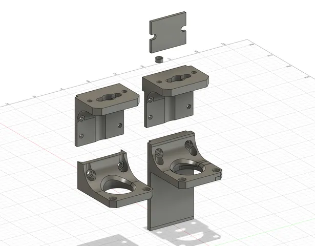
On the printer plate there are two holes already prepared, third (one of screws holding the PSU underneath) need to be unscrewed. Put the nuts into chain_plate_bottom and screw chain tip to it using 2x M3 6mm screws. Do the same with chain_plate_top on the another side of the chain.
Now You can solder second JST connector on another side of the chain. Hole in bed PCB allows it to pass to be plugged into its place. Now install such prepared setup to the printer body. Using two holes in the plate (2x M3 8mm + washer and nut underneath) and third for PSU. Make sure that bed POM wheels will be able to pass between chain plate and V-slot rail without issues. Now flop the printer on the side again and thread and plug Your new connector through and into PCB. Holding two pieces together, screw them to the bed frame like on the photo. Plug another side of the cable bundle into motherboard.
It should be done. Make sure that bed can travel smoothly and there is no grinding/issues with its movement along with the chain. In the most back position of the bed (endstop) there might happen that one of the nuts holding bed plate to the carriage is lightly catching against the chain. It require a little bit of adjustment, but otherwise do not case issues. All depends on how Your plastic chain was manufactured and if its is straight or lightly bending.
Turn on Your printer and check if bed is heating up correctly along with the temperature readings.
Tags
Model origin
The author marked this model as their own original creation.