CAUTION: WORK IN PROGRESS
This thing is work in progress. It works good for me, but that does not mean I got every case. I will leave this as work in progress as long as I do not get 10 makes and some feedback.
You can help make this thing better, print it, build it, test it and tell me what you think, where you ran into problems what you liked, what you did not like. Also let me know if the instructions are not clear at any point.
The first time I tested this antenna I was blown away, and I hope I can share this experience with you!
About
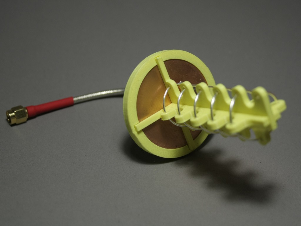
This thing will generate an antenna "frame" and a winding template for your custom helix antenna. Helix antenna are easy to build, polarized, directional antennas with high gain.
The default settings will generate all parts for a right hand polarized, 5.8GHz, 5 turn Helix Antenna with ~10dBi gain, 1mm diameter antenna wire and a beam with of ~50 degrees, to be used for FPV.
More turns means higher gain, but also results in a narrower beam.
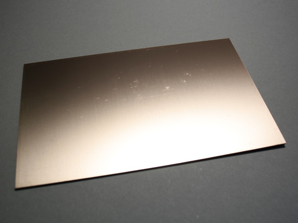
The use of a reflector is highly recommended and can be as easy as a copper PCB. either round or square. More information regarding reflectors may be found in this paper
The winding template changes depending on selected polarization. Depending on how you assemble the frame you can use it for the right or left hand polarized antenna.
Use this great calculator to get all the base values for your helix antenna. It will also show you the gain of your antenna and beam width.
The customizers default settings will generate a round reflector frame, you can check out my tool for cuttinig discs from square stock (https://www.thingiverse.com/thing:2508729)
Tools
For this project you will need the following tools:
* Snips
* Hobby knife
* Soldering Iron & solder
* Dremel / Rotary tool
Materials
Other than the 3D printed parts you will need the following materials:
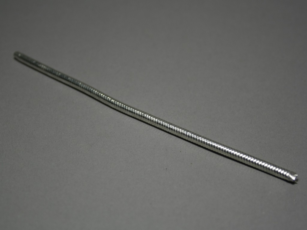
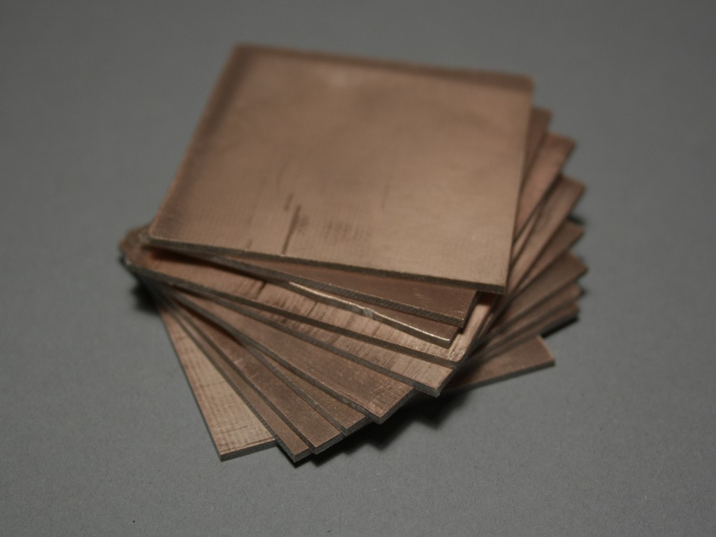
- Antenna Wire - I used 1mm diameter silver coated copper wire. Diameter is not that critical, and the material should be single core and you should be able to easily solder to it. * Reflector - I used Bungard double sided copper PCB's. Again, the material and thickness is not that important.
- Coaxial Cable - again, does not matter too much, as long as it has an impedance of 50 Ohms. I tried it with the flexible RG58 but also with the semi rigid RG402 which in my opinion is the better choice for on goggle mounting.
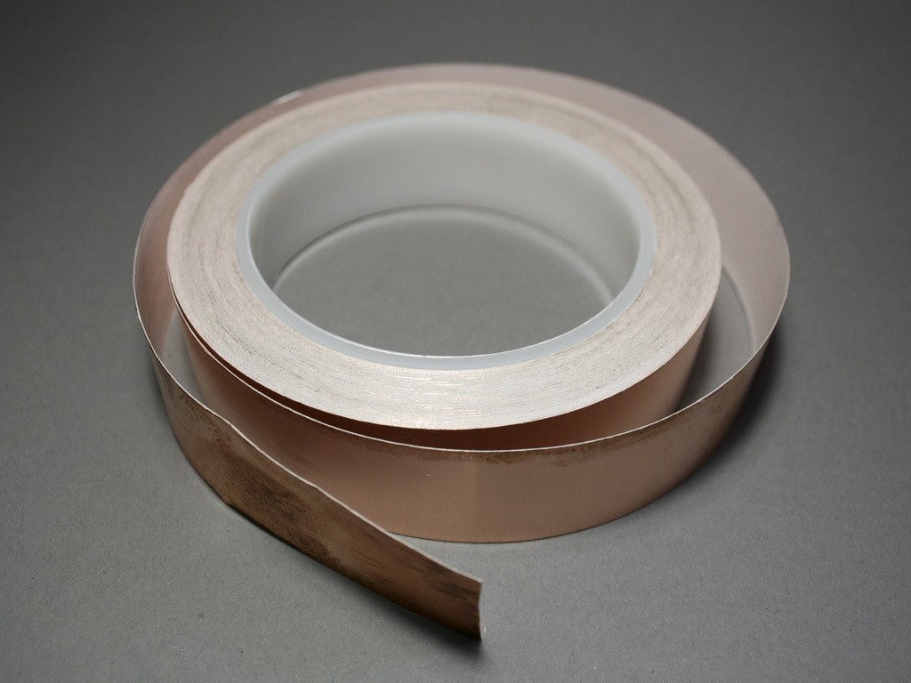
- Wave Trap - some solderable sheet of metal. I used copper tape and stacked multiple layers, again material should not matter too much, as long as it is not too thick (~0.5mm).
- Heat Shrink - I like to color code my antennas, red heat shrink for right hand polarized and b*lue for **l*eft hand polarized.
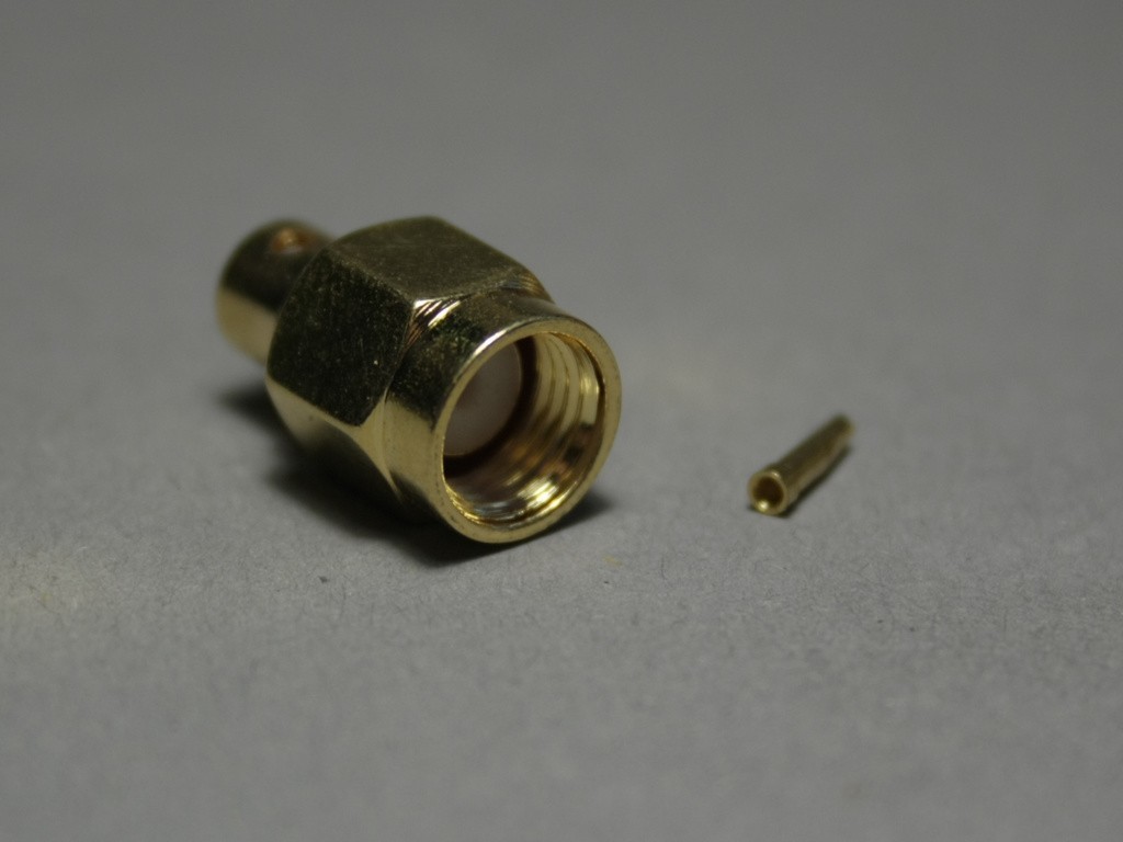
- SMA / RP SMA connector - depending on the receiver you are using you will need an appropriate SMA connector.
Preparation
If you do not use the same materials as I do, or want to use different specs, chances are, that you will need to change one or more parameters in the customizer. Give the customizer some time for rendering. The helix is quite complex to render, so it might take some time (took 30 minutes when I rendered the attached stl's from the default settings.)
Polarization
The polarization is only important for the winding template, all other parts may be used for both, left and right hand polarized antennas. Adjust the polarization value in the General Tab.
Frequency, Turns and Wire Diameter
If you intend to use a different frequency than 5.8GHz or a different number of turns than 5, head over to the calculator and fill in the following values in the General Tab of the customizer:
* turns: Amount of turns
* D: Inner Diameter of hte antenna
* d: Outer Diameter of the antenna wire, adjust this for your printers tolerances
* L: The length of the helix
Reflector Material and shape
In the Reflector Cover Tab, adjust reflectorThickness to the thickness of your reflector material. Adjust reflectorDiameter to at least the minimum diameter given by the calculator from above. A circle is recommended but square shape may also be used, if you are to lazy to go for a round shape ;-) Adjust reflectorShape accordingly.
Coaxial Cable
Again, in the Reflector Cover Tab, adjust coaxialDiameter to the thickness of your coaxial cable (with shielding, but without insulation).
Tolerances
Should your parts not fit well enough, check the Tolerances Tab and adjust values accordingly.
Parts
In the General Tab you will also find a dropdown with the parts to render. When rendering all parts it may take some time and the customizer might time out - because of the rather complicated winding template. I recommend reviewing with the Frame Parts selection.
Printing
The customizer will generate one file per part and one file with all the parts including winding template and another file with only the frame parts in case you already have your winding template.
Top and bottom frame part may be used for left and right hand polarized antennas, you only need to turn one of the pieces by 180 degrees before sliding it together.
I recommend printing the first layer rather slowly (20mm/s) to give the slopes of the frame a good chance of adhesion to the build plate.
Assembly
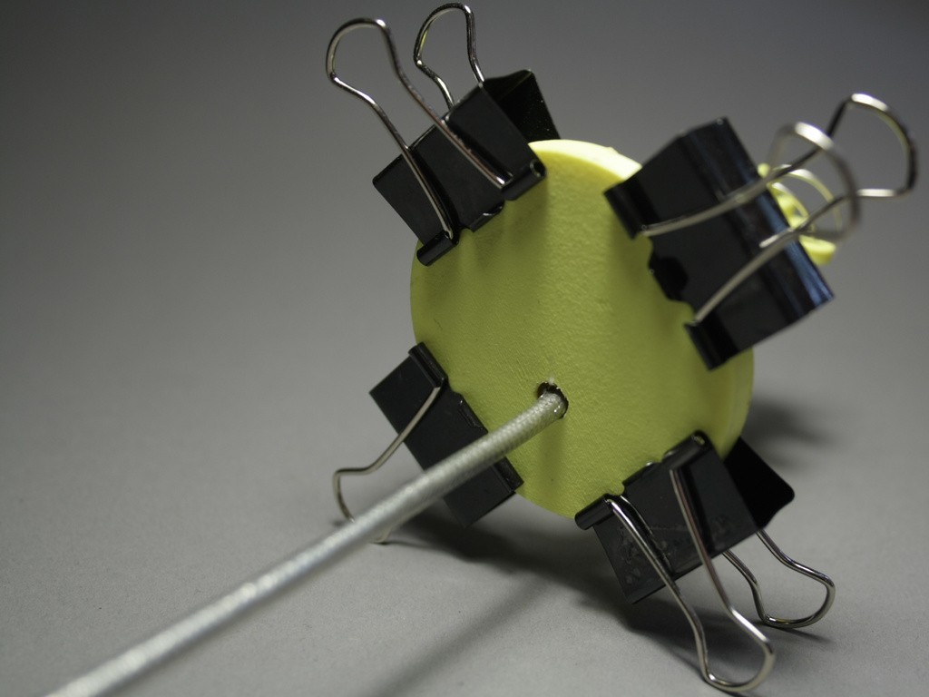
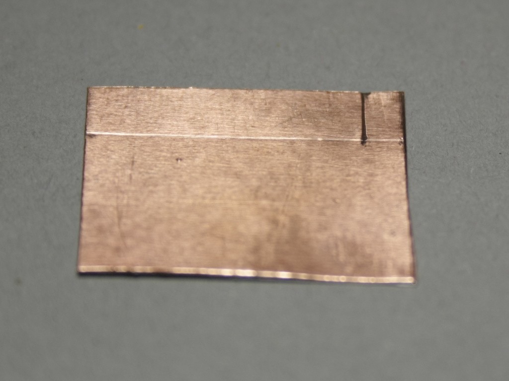
Step 1: Reflector
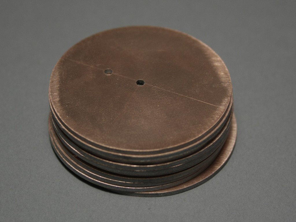
While the parts are printing you can already start by preparing the reflector. I decided to go with a round reflector with a diameter of 49mm, this is bigger than the recommended minimum diameter from the calculator and allows me to get 6 reflectors out of one PCB, without wasting too much material.
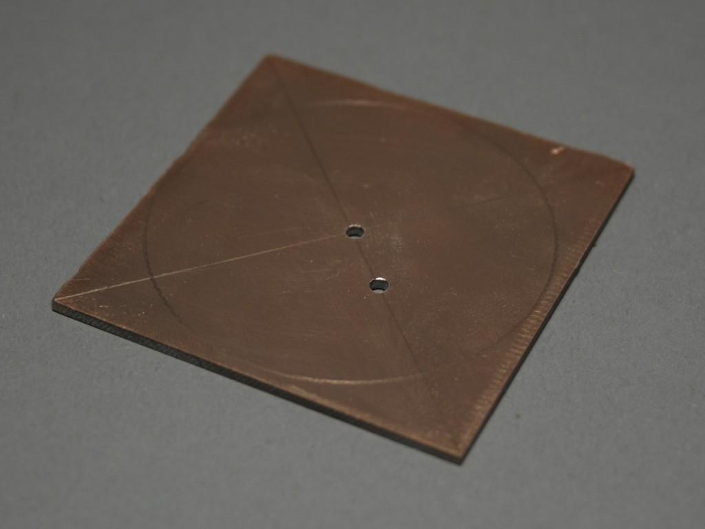
Mark the center of your reflector, also mark the hole for the coax cable (innerDiameter + wireDiameter) / 2. If you are going for a round reflector you can use my disc shaper tool (https://www.thingiverse.com/thing:2508729) drill a 2mm hole in the center and for the coax. Increase the hole for the coax until it fits snuggly, with the shielding but without the outer insulation.
Lengthen the coax cable, strip the shielding and inner insulation on one side about 5mm, stick it through the hole in your reflector and solder the shielding to the reflector. If you are using a double sided copper PCB as I do here, make sure to solder the shielding to both sides of the PCB.
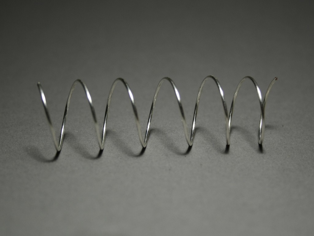
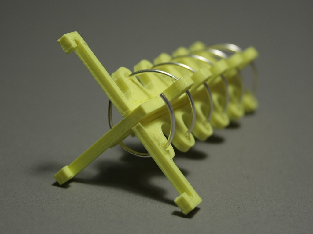
Step 2: Winding the Antenna
Once your winding template has finished you can start winding the antenna. Stick the wire in the little hole on the bottom, and start winding the wire slowly around the template. Keep it as tight as possible. Once you are done, use your snips to cut away the bottom part and turn the antenna off the template. The antenna windings might compress back a bit so gently pull them apart.
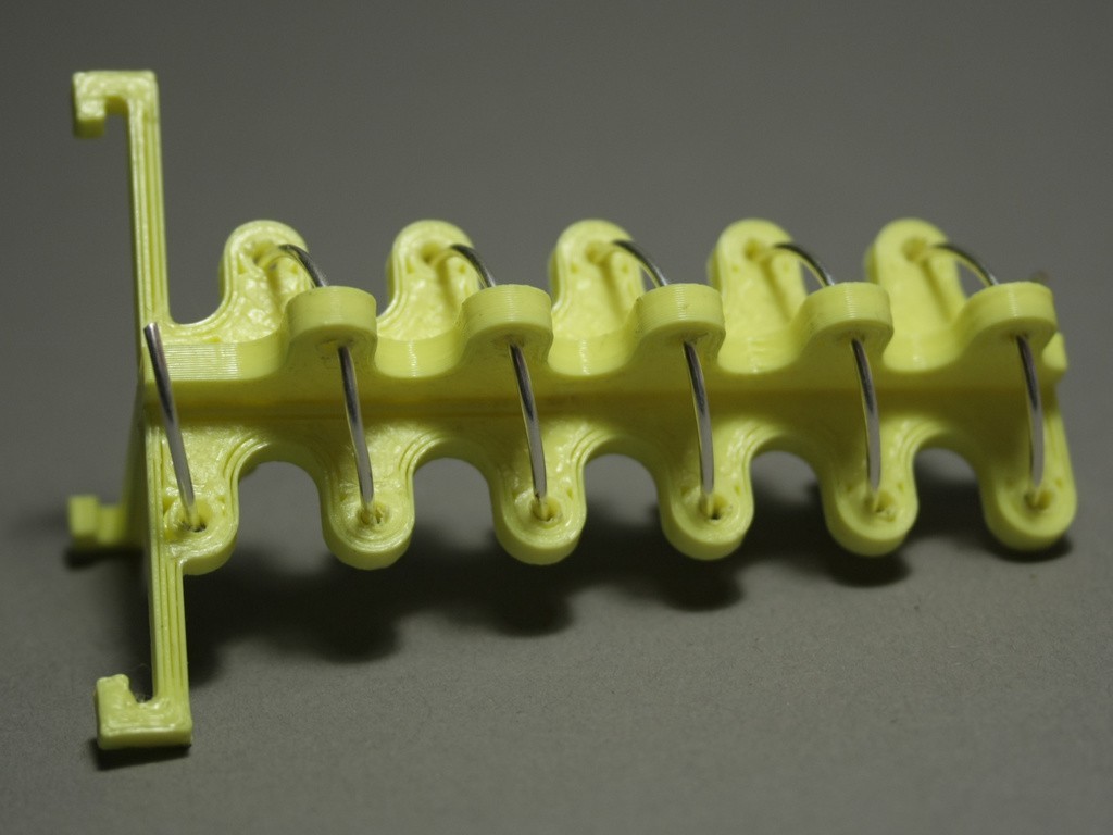
Step 3: Antenna support
Assemble top and bottom part of the antenna support, make sure that all the holes are clear and you have enough space for the wire. Start turning the antenna through the holes, until you reach the bottom.
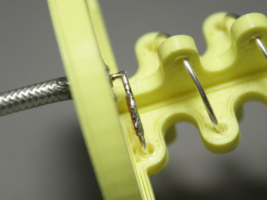
Step 4: Enclosure
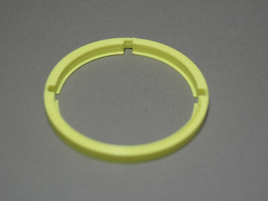
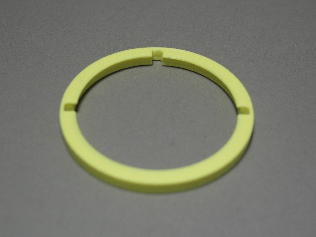
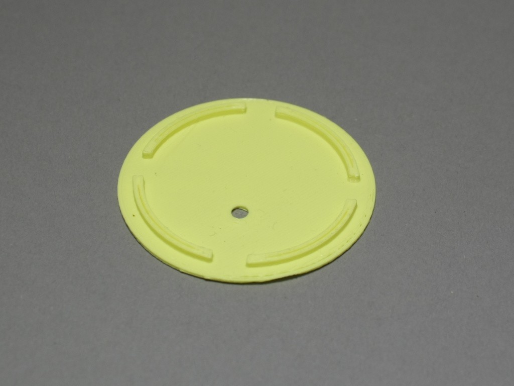
slide the reflector into the groves of the antenna support, add the ring with the slits from the top and the cover from the back. At this point you can glue ring and cover shut.
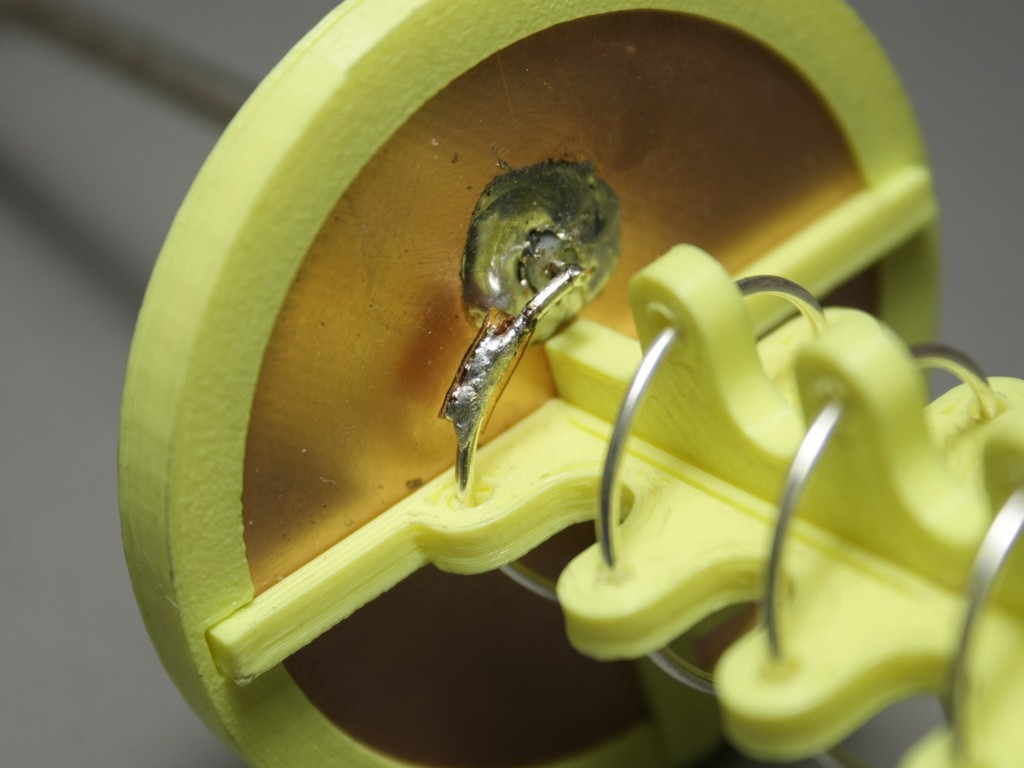
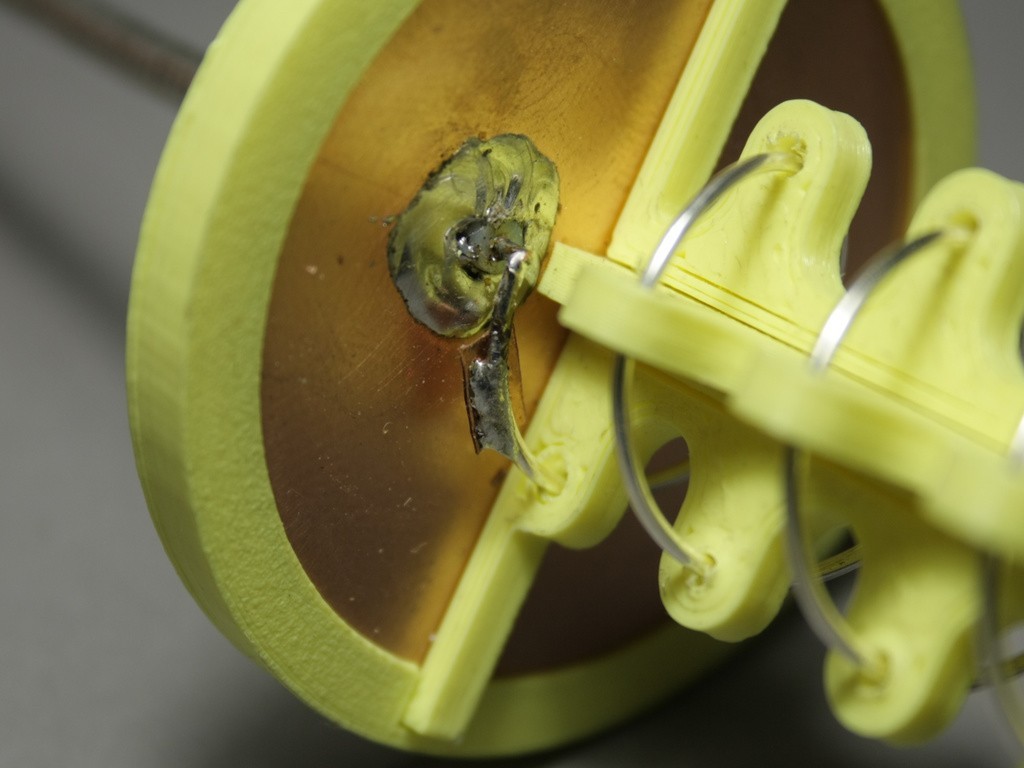
Step 5: Soldering Antenna
Solder the Antenna wire to the core of the coaxial cable. Make sure that the first 1/4 loop is at a height of 2.5mm from the reflector to the center of the wire (Feed point height).
Cut the center pin of the coax to height.
Step 6: Wavetrap
Cut the wavetrap to size (6.5mm x 3.2mm for 5.8GHz or Length in cm = 3720 / f in MHz, Width in cm = 1860/f in MHz) and solder it to the the center of the first 1/4 turn of your antenna.
Step 6: SMA / RP SMA
Strip the shielding and inner insulation from the coax cable on the other side about 3mm. Solder the center pin to the inner core of your coax. If you want to use heat shrink put it on now. Plug in the coax with the center pin soldered to the plug. Solder the shielding to the plug and use hot air or your lighter to shrink the heat shrink.
Step 7: Cleanup
Should the wire of the antenna be longer than the top hole, simply snip it. As last check, make sure you did not short out the antenna anywhere, therefore simply check for continuity on the SMA Connector.
That is it, you now have build your own helical antenna, now got out, test it and let me know what you think.
Results
I first build the square version you can see in the images. I went out and tried it out and was blown away by the results, 750m with a transmitter on 25mW and a clover leaf antenna.
Massive penetration, having some trees in line of sight was no problem, also the image was crystal clear almost all the time.
Shout outs
Massive shout out to IBCrazy from RCGroups who came up with the wave trap and made the helix antenna popular for FPV.
References
RCGroups' IBCracy helical Antenna and Wavetrap Tutorial
:format(webp)/https://fbi.cults3d.com/uploaders/13691234/illustration-file/08a4dfcf-f895-418f-b6c0-2d5b3262b9f2/c914504575303f349590e3ad7c10bee7_display_large.jpg)