Skip to content

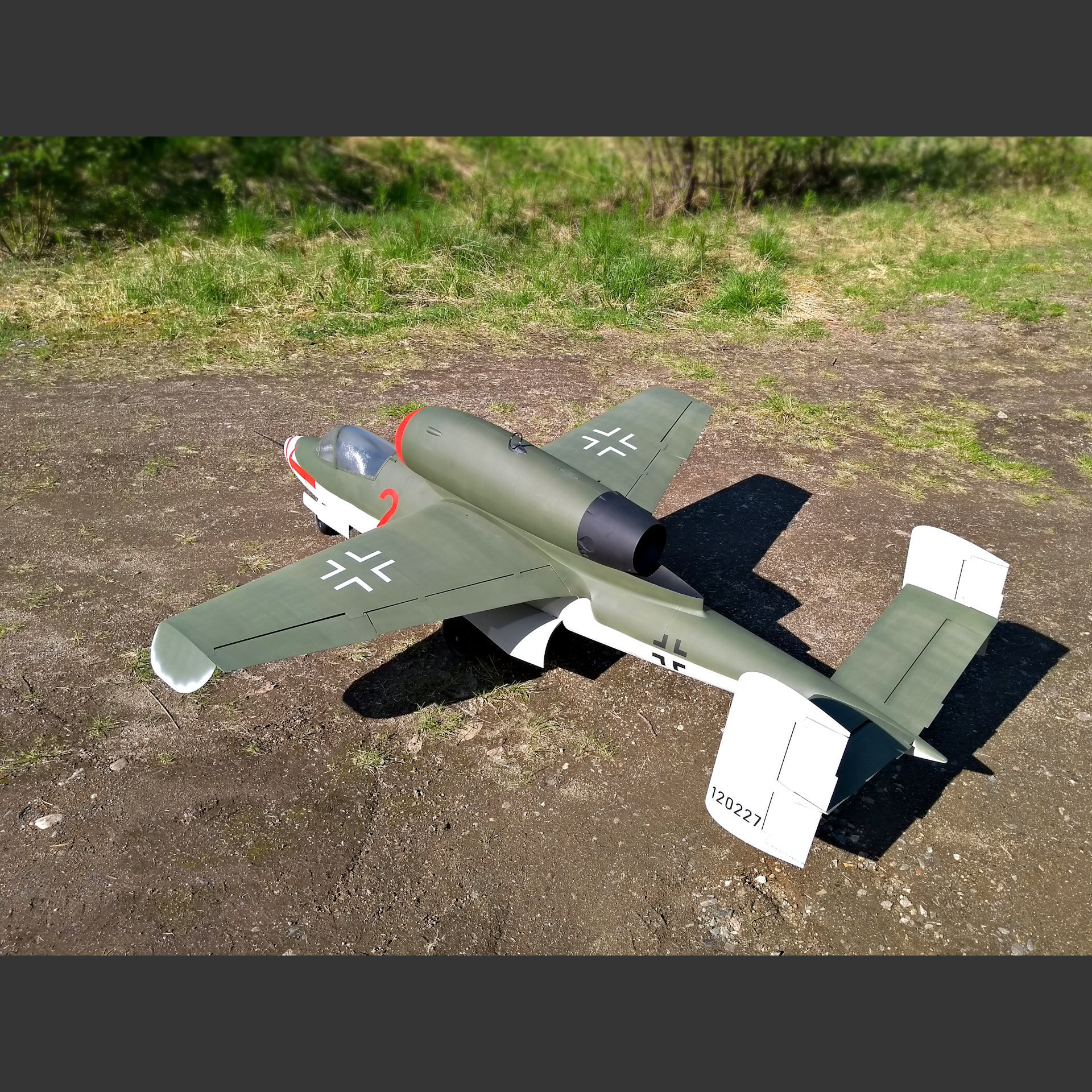
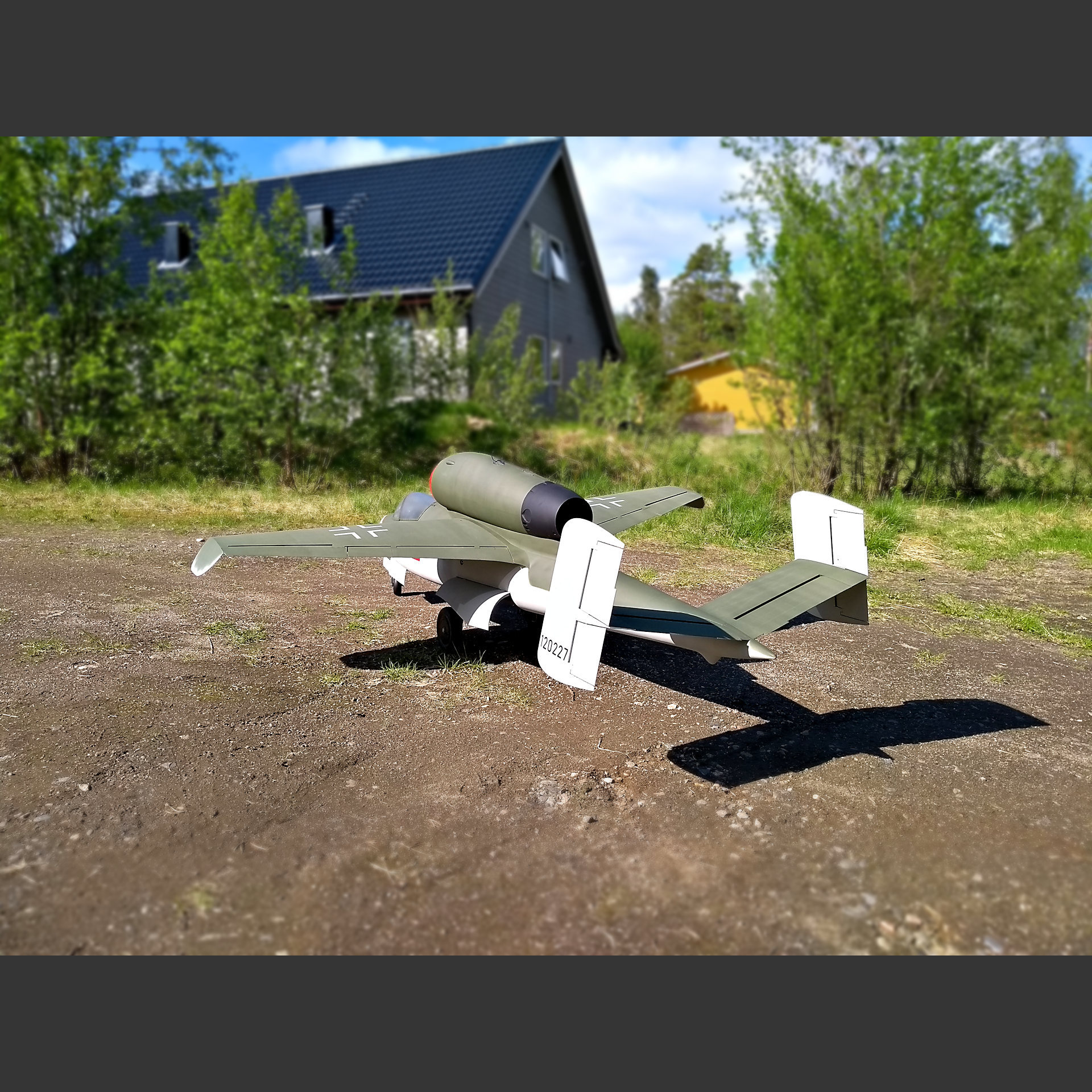
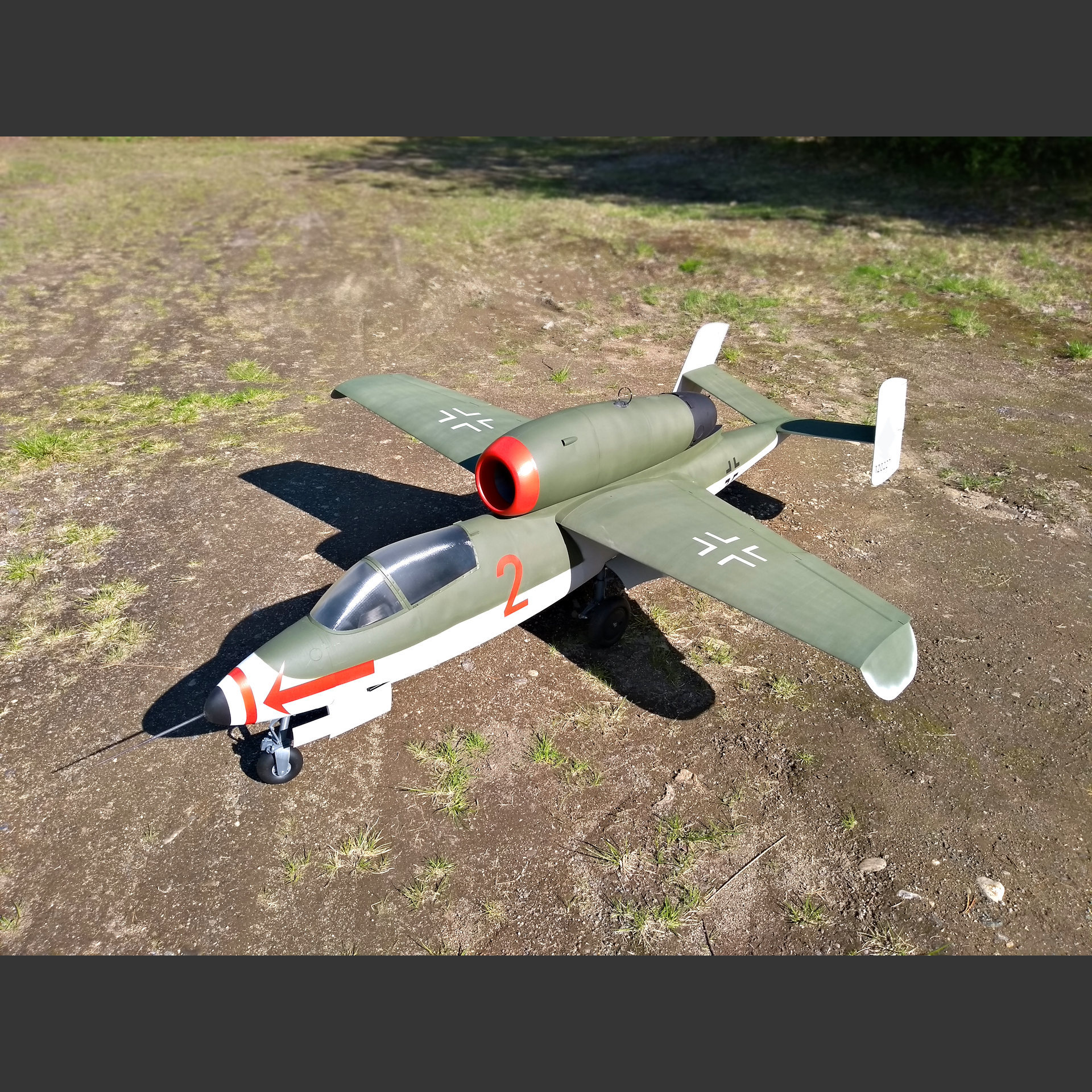
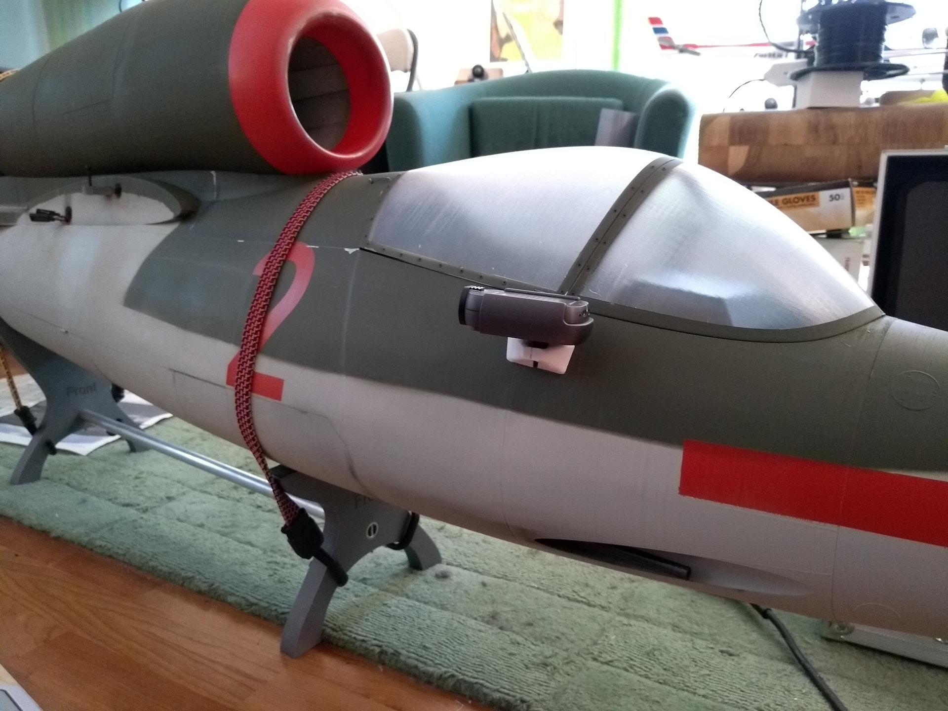
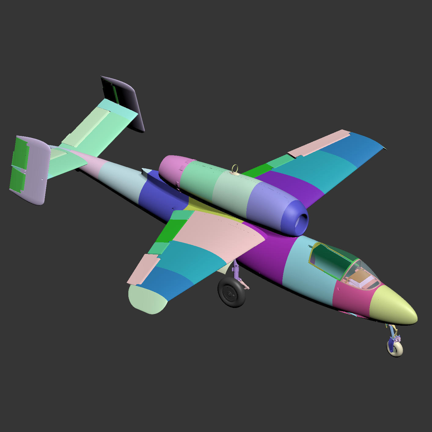
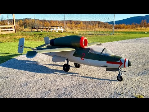
Giant 1:4,5 scale Heinkel He-162 A2 RC jet model

Advertising
?
Creation quality: 5.0/5 (5 votes)
Evaluation of members on the printability, utility, level of detail, etc.

  • 65k views
  • 172 likes
  • 154 downloads
  • 2 collections
  • 47 comments

License
3D design format
STL, TXT, and ZIP Folder details Close
  • Aileron01.STL
  • Aileron02.STL
  • Aileron03.STL
  • Aileronservocover01.STL
  • Aileronservosupport01.STL
  • Antenna01.STL
  • Antenna02.STL
  • Antenna03.STL
  • Ballink01.STL
  • Batterytray01.STL
  • Batterytray02.STL
  • Cameramount-front.stl
  • Cannon01.STL
  • Canopy01.STL
  • Canopy02.STL
  • Canopyframe01.STL
  • Canopyframe02.STL
  • Canopyframe03.STL
  • Canopyhinge01.STL
  • Controlrodsupport01.STL
  • Drumbrake01.STL
  • Drumbrake02-Lining.stl
  • Drumbrake03-cam.stl
  • EDF-impeller01.STL
  • EDFhousing01.STL
  • Elevator01.STL
  • Exhaust01.STL
  • Exhaust02-turbine.STL
  • Flap01.STL
  • Flap02.STL
  • Flap03.STL
  • Flapservomount01.STL
  • Fuselage01.STL
  • Fuselage02.STL
  • Fuselage03.STL
  • Fuselage04-brace.STL
  • Fuselage04.STL
  • Fuselage05.STL
  • Fuselage06.STL
  • Fuselage07.STL
  • Fuselage07.zip
  • Fuselage08-tabs.STL
  • Fuselage08.STL
  • Hstab01.STL
  • Hstab02.STL
  • Instrumentpanel01.stl
  • Instrumentpanel02.stl
  • Intake01-EDF.STL
  • Intake01-Turbine.STL
  • Intake02.STL
  • Link01.STL
  • Link02.STL
  • Link03.STL
  • Maingearcover01.stl
  • Maingearcover02.stl
  • Maingeardoor01.stl
  • Maingeardoor02.stl
  • Maingeardoorhinge01.STL
  • Maingeardoorhinge02.STL
  • Maingeardoorlink01.STL
  • Mainstrut01.STL
  • Mainstrut02-left.STL
  • Mainstrut02-right.STL
  • Mainstrut03.STL
  • Maintire01.STL
  • Mainwheel01-Williamsbros.STL
  • Mainwheel01.STL
  • Mainwheel02-Williamsbros.STL
  • Mainwheel02.STL
  • Mainwheel03-Williamsbros.STL
  • Nacelle01-BigESC.STL
  • Nacelle01.STL
  • Nacelle02-universal.STL
  • Nacelle02.STL
  • Nacelle03-universal.STL
  • Nacelle03.STL
  • Nacelle04.STL
  • Nose01.STL
  • Nosegear01.STL
  • Nosegear02.STL
  • Nosegear03.STL
  • Nosegear04.STL
  • Nosegear05.STL
  • Nosegear06.STL
  • Nosegear07.STL
  • Nosegear08.STL
  • Nosegear09.STL
  • Nosegear10.STL
  • Nosegear11.STL
  • Nosegear12.STL
  • Nosegear13.STL
  • Nosegeardoor01.STL
  • Nosegeardoor02.STL
  • Nosewellcover01.STL
  • Nosewheel01.STL
  • Pilotstand01.STL
  • Printsettings.txt
  • Rudder01.STL
  • Rudder02.STL
  • Servomount-Elevator01.STL
  • Servomount-Elevator02.STL
  • Shockpiston01.STL
  • Shockrodend01.STL
  • Shockspacer01.STL
  • Stand-front.STL
  • Stand-rear.STL
  • Vstab01.STL
  • Vstab02.STL
  • Vstab03-cameramounthole.STL
  • Vstab03.STL
  • Vstabcovers01.STL
  • Wing01.STL
  • Wing02.STL
  • Wing03.STL
  • Wingjoiner01.STL
  • Wingtip01.STL

Learn more about the formats

Last update 2023-05-01 at 20:38
Publication date 2019-06-21 at 20:57
Design number 61484

3D printer file info

3D model description

Temporary safety warning: I recommend stiffening the wheel bay doors with some carbon tow or cloth diagonally to prevent deforming at high speed. I want to design stiffer doors but as a temporary fix I recommend the reinforcements.


Update: An error was discovered in Wing01.STL that prevented the flap from moving. This happened because I didn't finish an update before I uploaded. I'm very sorry for this. The fix if you have already printed parts can be found in the RCGroups thread in post 603, so it's not necessary to print a whole new wing. Basically it involves cutting a small square from the flap and gluing in a small piece to the hinge point on the wing to fill the void:

https://www.rcgroups.com/forums/showthread.php?3116478-3D-printed-He-162-for-120-mm-EDF/page21&perpage=30#post48352905

The new Wing01.stl you download from here on Cults now is changed to allow the new flap to rotate.


1:4,5 scale model of the Heinkel He-162.

Length: 1996 mm (without pitot tube)
Wingspan: 1580 mm
Flying weight: 7,5 kg
Power: ~4000 W

Minimum printer size for the biggest parts: 280x280x300 mm
Many parts will print on smaller 200x200x180

CG: 83 mm - Should be slightly forward with gear down and slightly aft with gear up
Elevator throw: 20 mm up and down
Aileron throw: 20 mm up and down
Rudder throw: 12 mm left and right

Prototype videos:
https://youtu.be/EDEhikNloU8
https://youtu.be/c0MWYCIPg6g
(Note that the prototype did not have reinforced landing gear like the files here. I'm reprinting with the reinforcements)
Final version video with reinforced undercarriage:
https://www.youtube.com/watch?v=bHlbqoq0Mpk

Very good stall characteristics and gentle handling in flight. The prototype had a top speed of 228 km/h with the 3D printed EDF. There is no bad handling because of the high thrust line because it is compensated for in the design.

The EDF intake is larger than scale for more airflow to the 120 mm EDF. The turbine intake is closer to scale size. I have no intention of trying turbines myself but There is room in the fuselage for all kinds of tanks. I can design a turbine nacelle if there is a need for one with a larger internal cavity than the duct.

I added a separate Exhaust piece for small turbines for those that want to try that. Exhaust02-turbine has 6,6mm slots in the sides for glueing in 6 mm or 1/4" plywood mounting rails for turbines like Kingtech K45 at the proper angle (2Β° down thrust). The top of the plywood rails will be the center of the duct.

The canopy has 4mm holes on each side in the front for adding 4mm latching mechanism. You'll need ~4x30mm rods with a 2mm hole drilled perpendicular for ~2x10mm rods (handles to fit into. You also need 3mm-4mm diameter springs if you want the latch to lock in place with spring tension. The same

Warning, skills like basic metalwork and brazing (silver soldering) is required to finish this model, as well as general model setup know-how. Don't buy this if you don't know how to do DIY stuff like that, or are not willing to figure it out. If precise center drilling isn't possible then a pre made shaft coupler can be used between the threaded rod and actuator shaft instead, for example a 3x5mm (or 3x4 threaded to M5) here:
https://rover.ebay.com/rover/1/711-53200-19255-0/1?ff3=4&toolid=11800&pub=5575353675&campid=5338226872&mpre=https%3A%2F%2Fwww.ebay.com%2Fitm%2F5-10pcs-Brass-Shaft-Coupling-Coupler-Motor-Transmission-Connector-2-3-4-5-6MM%2F223717654597

I mistakenly linked to the wrong retract sequencer before. It should be V1, not V2.


Build notes:
Make sure you don't glue the h-stabs together and to the fuselage before the elevators are ready and assembled together with the h-stabs. If you glue them in too early you will have to figure out a way to install the elevators afterwards since the hinges are protruding from the nds of the elevator. In such a case I suggest printing each elevator as three parts and glueing them together in place in the elevator slot.

The y-shaped Fuselage04-brace under the main langing gear bay should have a ~500 mm 4mm rod of carbon through it and into Fuselage03 and Fuselage05 as one illustration shows, to strengthen the belly of the fuselage and tie the whole thing together. If this is forgotten I suggest simply adding some carbon or fiberglass tow or ribbon along the bottom of the fuselage.

Most control surface hinge pins should be 3 mm carbon rods. How it goes together is obvious when you have the parts in hand.

The elevator uses 6 mm tube and 6x15x5 ball bearings for the inside hinge point where the control arm will be. You must make and install the control arm before you glue the horizontal stabs to the fuselage or else it will be more difficult.


Safety warnings:
-The EDF s a very highly loaded assembly at high speed so it's important that you know what you are doing.
-Make sure the integrity of the printed impeller is good before trying to run it.
-Always wear protective glasses when test runnin the fan. Always protect your eyes.
-Do NOT run the fan at high power while holding in your hand.
-Keep your hands and any loose items away from the fan when running. It WILL shred your fingers if they get sucked in, and the suction force is very strong. If something gets sucked in it can damage the impeller and potentially shatter, throwing loose debris out.


Landing gear parts:
Uses retract actuators from JP to retract the landing gear which is integrated: http://www.hobby-china.com/control-box-v1-for-gear-operation-jp-hobby.html
http://www.hobby-china.com/motor-parts-for-jp-aer-7-3-jp-hobby-alloy-electric-retracts-for-7-8-kg.html
2x 130 mm shocks: https://www.banggood.com/4PC-180007-130MM-Aluminum-Alloy-Front-Rear-Shock-Absorber-For-HSP-Rc-Car-Climbing-Rock-Crawler-p-1305169.html?ID=232&cur_warehouse=CN
2x 1,4x10x50 mm springs for the main gear: https://www.ebay.com/itm/1-4mm-WD-9mm-OD-Stainless-Steel-Compression-Spring-Compressed-Pressure-Springs/272632001985
0,8x9x60 mm tension spring for the nose gear (I made mine from spring stock)
M5 threaded rod stock and M5 nuts to make actuator lead screws from
Williams Bros 5-1/4 tires can be used instead of the printed tires. Ask WB to sell tires only to avoid having to remove the hub: http://www.wmbros.com/store/p53/Smooth_Balloon-II%2C_5-1%2F4%22_Diameter%2C_1_Pair.html
Dubro smooth 3-1/4" nose wheel:
https://www.ebay.com/itm/372109961103
4x 47ODx3,5 mm O-rings for the brakes: https://www.ebay.com/itm/253621698783

Requires the following carbon fiber tubes and rods:
1x 16x14x770 mm tube for the wings
2x 16x14x84 mm tubes for the lower main gear struts
2x 18x16x157 mm tubes for the upper main gear struts
1x 8x6x300 mm tube for the wings
1x 8x6x167 mm tube for the nose gear strut
1x 6x4x900 mm tube for elevator control
Various lengths of 6 mm tube or rod for strengthening the landing gear mount area
Various lengths of 3mm and 4 mm carbon fiber rod for hinging and reinforcement. The control surfaces use 3mm carbon rods. You'll need ~5 1m rods.

Screws:
Various M3 screws and nuts from 8 mm length to 40 mm length
Various M2 screws from 10 to 20 mm length
M3x5 and 12 mm grub screws
M6x80 mm screws for the main gear strut mounts
M6x50 mm hex head bolts for the main wheels

Ball bearings:
12x 6x15x5 mm for the main gear and elevators
4x 4x11x4 mm for the nose gear

Servos:
3x JX DHV56MG for the nose steering and wheel brakes: https://www.banggood.com/4PCS-JX-Servo-DHV56MG-5_6g-DS-Digital-Coreless-MG-Metal-Gear-HV-Servo-1_2kg-0_10sec-For-RC-Airplane-p-1430838.html?cur_warehouse=CN7x Corona CS-238MG (or similar size servo with 4+ kgf/cm torque) for all control surfaces. Flaps and elevator can use standard servos instead: https://www.banggood.com/Corona-CS238MG-Thin-Metal-Wing-Analog-Servo-p-1049129.html
1x "9g" servo for the nose gear door

Power for the printable EDF unit:
2x 6S 5000 mAh lipos (Gens Ace 45C recommended)
Castle Creations Talon HV 120 ESC
Het 800-73-590kv motor with heatsink:https://www.turbines-rc.com/en/50-56mm-brushless-motors/285-typhoon-het-edf-800-73-motor-50mm-590kv.html
https://www.turbines-rc.com/en/heat-sink/1075-heat-sink-75mm-for-50mm-motor-and-ejets-jetfan-120-edf.html

The stand uses a 16x585 mm tube as the center member. I used locally sourced aluminum tubing. The stand is supposed to support the plane immediately aft of the gear wells and at the joint between Fuselage02 and Fuselage03.

If the 3D printable fan is used, the recommended HET motor should also be used with the heatsink. The motor shaft should have a hole drilled half way through it for one of the M3-16 mm impeller grub screws, because heat soak from the motor can cause the impeller to come loose if just a flat spot is used. The prototype fan pulled 100 A at full throttle on a fresh 12S charge when installed in the HE-162.

3D printing settings

PLA is fine for all parts. Your mileage may vary due to temperature requirement and personal preference.

As a weight reference, my Fuselage02 weighs 151 g after the two support pieces are removed.

Open the factory file to see recommended print settings for the some of the parts.

Wings, tail and fuselage main parts should be printed with 0,3 mm wall thickness and single perimeter only. I recommend 0,12 mm layer height. Thicker print width is not recommended due to weight and balance, but 0,4 mm is possible.

The same goes for links and other small critical parts.

EDF impeller and housing should be printed with 6 top and bottom layers and 7 perimeters.


The reason for different processes at different heights on some parts is to either reduce weight by eliminating sloppe zig-zags or to increase strength in certain areas with extra wall thickness for example. If your slices is incapable of making different processes then you either need to change slicer or find your own settings that give a compromise in weigh and strength. These settings were close to the same settings used in Simplify 3D to print the prototypes.

Suggested settings for the thin wall parts without infill:
Aileron01: 0,3 mm single perimeter. 0% infill. 0,12 mm layer height. 6 top and 2 bottom layers.
Aileron02: 0,3 mm single perimeter. 0% infill. 0,12 mm layer height. 6 top and 2 bottom layers.
Aileron03: 0,3 mm 2 perimeter. 0% infill. 0,12 mm layer height. 6 top and 3 bottom layers.

Canopy01: 0,4 mm single perimeter vase mode. 0% infill. 0,24 mm layer height. 0 top and 2 bottom layers.
Canopy02: 0,4 mm single perimeter vase mode. 0% infill. 0,24 mm layer height. 0 top and 2 bottom layers.

Elevator01: 0,3 mm single perimeter. 0% infill. 0,12 mm layer height. 6 top and 3 bottom layers.

Exhaust01: 0,3 mm single perimeter. 0% infill. 0,12 mm layer height. 6 top and 4 bottom layers.

Flap01: 0,3 mm single perimeter. 0% infill. 0,12 mm layer height. 6 top and 3 bottom layers.
Flap02: 0,3 mm single perimeter. 0% infill. 0,12 mm layer height. 8 top and 2 bottom layers.
Flap03: 0,3 mm single perimeter. 0% infill. 0,12 mm layer height. 6 top and 3 bottom layers.

Fuselage01: 0,3 mm single perimeter. 0% infill. 0,12 mm layer height. 8 top and 6 bottom layers.
Fuselage02: 0,3 mm single perimeter. 0% infill. 0,12 mm layer height. 8 top and 4 bottom layers.
Fuselage03 process 1 (0-120 mm height): 0,3 mm single perimeter. 0% infill. 0,12 mm layer height. 6 top and 2 bottom layers.
process 2 (120-145 mm height): 0,3 mm 3 perimeter. 0% infill. 0,12 mm layer height. 6 top and 2 bottom layers.
process 3 (145-end height): 0,3 mm single perimeter. 0% infill. 0,12 mm layer height. 6 top and 2 bottom layers.
Fuselage04 process 1 (0-149 mm height): 0,3 mm single perimeter. 0% infill. 0,12 mm layer height. 10 top and 2 bottom layers.
process 2 (149-297 mm height): 0,3 mm single perimeter. 0% infill. 0,12 mm layer height. 2 top and 2 bottom layers.
process 3 (297-end height): 0,3 mm single perimeter. 0% infill. 0,12 mm layer height. 10 top and 2 bottom layers.
Fuselage04-brace: 0,3 mm single perimeter. 0% infill. 0,12 mm layer height. 6 top and 2 bottom layers.
Fuselage05: 0,3 mm single perimeter. 0% infill. 0,12 mm layer height. 0 top and 2 bottom layers.
Fuselage06 process 1 (0-55 mm height): 0,3 mm single perimeter. 0% infill. 0,12 mm layer height. 6 top and 2 bottom layers.
process 2 (149-297 mm height): 0,3 mm single perimeter. 0% infill. 0,12 mm layer height. 0 top and 0 bottom layers.
Fuselage07: 0,3 mm single perimeter. 0% infill. 0,12 mm layer height. 6 top and 6 bottom layers.

Hstab01: 0,3 mm single perimeter. 0% infill. 0,12 mm layer height. 8 top and 4 bottom layers.
Hstab02 process 1 (0-25 mm height): 0,3 mm single perimeter. 0% infill. 0,12 mm layer height. 6 top and 3 bottom layers.
process 2 (25-30 mm height): 0,3 mm single perimeter. 0% infill. 0,12 mm layer height. 12 top and 12 bottom layers.
process 3 (30-end height): 0,3 mm single perimeter. 0% infill. 0,12 mm layer height. 6 top and 3 bottom layers.

Intake01: 0,3 mm single perimeter. 0% infill. 0,12 mm layer height. 10 top and 2 bottom layers.

Nacelle01: 0,3 mm single perimeter. 0% infill. 0,12 mm layer height. 8 top and 2 bottom layers.
Nacelle02: 0,3 mm single perimeter. 0% infill. 0,12 mm layer height. 6 top and 2 bottom layers.
Nacelle03 process 1 (0-10 mm height): 0,3 mm single perimeter. 0% infill. 0,12 mm layer height. 8 top and 4 bottom layers.
process 2 (10-180 mm height): 0,3 mm single perimeter. 0% infill. 0,12 mm layer height. 0 top and 0 bottom layers.
process 3 (180-end height): 0,3 mm single perimeter. 0% infill. 0,12 mm layer height. 8 top and 4 bottom layers.
Nacelle04: 0,3 mm single perimeter. 0% infill. 0,12 mm layer height. 6 top and 4 bottom layers.

Rudder01: 0,3 mm single perimeter. 0% infill. 0,12 mm layer height. 7 top and 3 bottom layers.
Rudder02: 0,3 mm single perimeter. 0% infill. 0,12 mm layer height. 7 top and 3 bottom layers.

Vstab01: 0,3 mm single perimeter. 0% infill. 0,12 mm layer height. 6 top and 3 bottom layers.
Vstab02: 0,3 mm single perimeter. 0% infill. 0,12 mm layer height. 6 top and 3 bottom layers.
Vstab03 process 1 (0-14 mm height): 0,3 mm single perimeter. 0% infill. 0,12 mm layer height. 6 top and 2 bottom layers.
process 2 (14-18 mm height): 0,3 mm single perimeter. 0% infill. 0,12 mm layer height. 6 top and 6 bottom layers.
process 3 (18-end height): 0,3 mm single perimeter. 0% infill. 0,12 mm layer height. 4 top and 0 bottom layers.

Wing01: 0,3 mm single perimeter. 0% infill. 0,12 mm layer height. 6 top and 6 bottom layers.
Wing02: 0,3 mm single perimeter. 0% infill. 0,12 mm layer height. 6 top and 6 bottom layers.
Wing03: 0,3 mm single perimeter. 0% infill. 0,12 mm layer height. 6 top and 2 bottom layers.
Wingtip01: 0,4 mm single perimeter. 0% infill. 0,12 mm layer height. 2 top and 2 bottom layers.

Other parts:
Nose01: 0,4 mm 2 perimeter. 0% infill. 0,12 mm layer height. 6 top and 6 bottom layers.

Canopyframe01: 0,48 mm 3 perimeter. 0% infill. 0,12 mm layer height. 6 top and 6 bottom layers.

Maintire01: 0,34 mm 2 perimeter. 7% infill. 0,12 mm layer height. 8 top and 4 bottom layers.

Mainwheel02: 0,3 mm 2 perimeter. 7% infill. 0,12 mm layer height. 8 top and 3 bottom layers.

Wingjoiner01: 0,35 mm 6 perimeter. 0% infill. 0,12 mm layer height. 13 top and 13 bottom layers.

High strength parts like landing gear struts and similar should be near solid, with four or more perimeters and higher than normal temp.

Advertising


Issue with this design? Report a problem.

Would you like to support Cults?

You like Cults and you want to help us continue the adventure independently? Please note that we are a small team of 3 people, therefore it is very simple to support us to maintain the activity and create future developments. Here are 4 solutions accessible to all:

  • ADVERTISING: Disable your banner blocker (AdBlock, …) and click on our banner ads.

  • AFFILIATION: Make your purchases online by clicking on our affiliate links here Amazon.

  • DONATE: If you want, you can make a donation via Ko-Fi πŸ’œ.

  • WORD OF MOUTH: Invite your friends to come, discover the platform and the magnificent 3D files shared by the community!


Sharing and downloading on Cults3D guarantees that designs remain in makers community hands! And not in the hands of the 3D printing or software giants who own the competing platforms and exploit the designs for their own commercial interests.

Cults3D is an independent, self-financed site that is not accountable to any investor or brand. Almost all of the site's revenues are paid back to the platform's makers. The content published on the site serves only the interests of its authors and not those of 3D printer brands who also wish to control the 3D modeling market.

100% secure payment by credit card, PayPal, Apple Pay, Google Pay, etc.
View all payment options.