Supplies.
I used the following supplies:
• Thick cyanoacrylate glue.
• Thin cyanoacrylate glue.
• Cyanoacrylate glue accelerant.
• Light machine oil.
• Salvaged CAT5 twisted pair 24AWG stranded wire (28AWG stranded wire is better for its flexibility).
• Solder.
Acquire, Print and Prepare the Parts.
This model uses the following non-3D printed parts:
• One 2 AAA battery holder with switch (search for "2 AAA Battery Holder with Switch").
• Two AAA batteries.
• One N20 6VDC 150RPM gear motor.
• Two salvaged tea lamp LEDs and flame lenses.(https://www.amazon.com/gp/product/B00T28FWVS/ref=ppx_yo_dt_b_asin_image_o00_s00?ie=UTF8&psc=1).
• Two clear bright red 3mm LEDs (my parts bin).
• Two 100ohm 1/4 watt resistors (my parts bin).
• Two micro roller switches (search for "CYT1096").
• One micro lever switch (search for "CYT1073").
• Two M2 by 10mm cap screws with nuts (local hardware store).
• Two M2.5 by 20mm cap screws with nuts (local hardware store).
• Wire (28AWG stranded is preferred, I used salvaged CAT5 24AWG stranded).
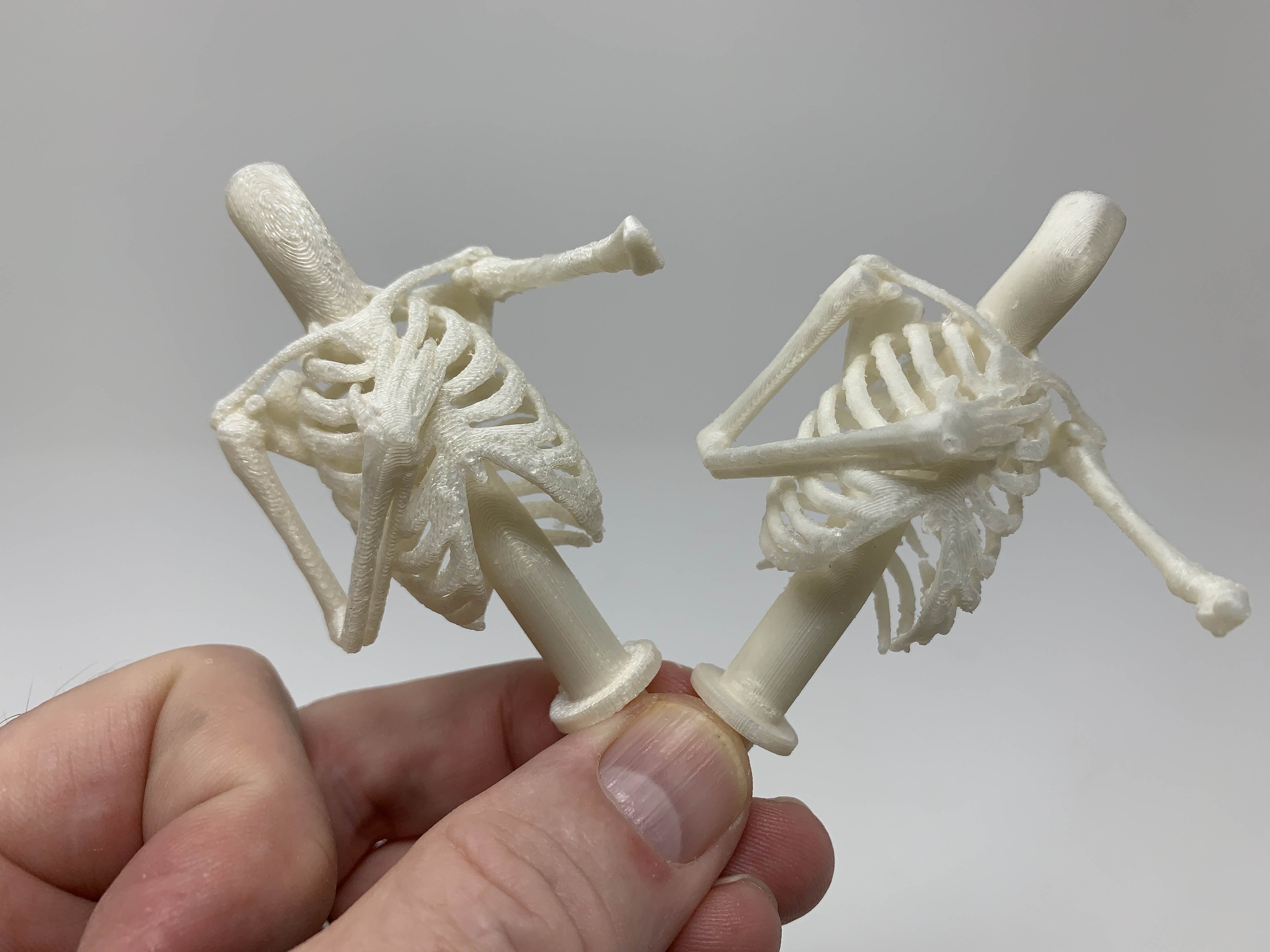
For the 3D printed parts, I've included the file "RIP 3D Printed Parts List" containing the part names, count, layer height, infill and support settings for the parts I printed. Note I printed "Skeleton, Head.stl" and "Skeleton.stl" with supports. I printed both of these parts with PVA (water soluble) support using the Cura 4.2 "Everywhere" support setting with excellent results. I also printed both of these parts with PLA support using the Cura 4.2 "Touching Buildplate" support setting with quite good results as shown in the "Skeleton.stl" comparison photograph. Keep in mind that when using PLA support, you must use the "Touching Buildplate" support setting or the skeleton "spine" will be blocked with PLA support filament and thus become incapable of accepting wiring for the head LED. There are two camshafts, "Camshaft 75.stl" and "Camshaft 150.stl", the first being for a 75RPM motor and the second a 150RPM motor.
This is a high precision print and assembly model using at times very small parts and in very tight spaces. Prior to assembly, test fit and trim, file, sand, etc. all parts as necessary for smooth movement of moving surfaces, and tight fit for non moving surfaces. Depending on you printer, your printer settings and the colors you chose, more or less trimming, filing and/or sanding may be required. Carefully file all edges that contacted the build plate to make absolutely certain that all build plate "ooze" is removed and that all edges are smooth. I used small jewelers files and plenty of patience to perform this step.
The model also uses threaded assembly, so I used a tap and die set (6mm by 1, 8mm by 1.25) for thread cleaning.
I used small dots of thick cyanoacrylate glue to attach the skeleton left arm to the torso, attach the handles and letters to the case, secure the wiring to the base and to secure threads if needed. I also used light machine oil for lubrication of the gears, pins and axles.
Salvage the Tea Lamps.
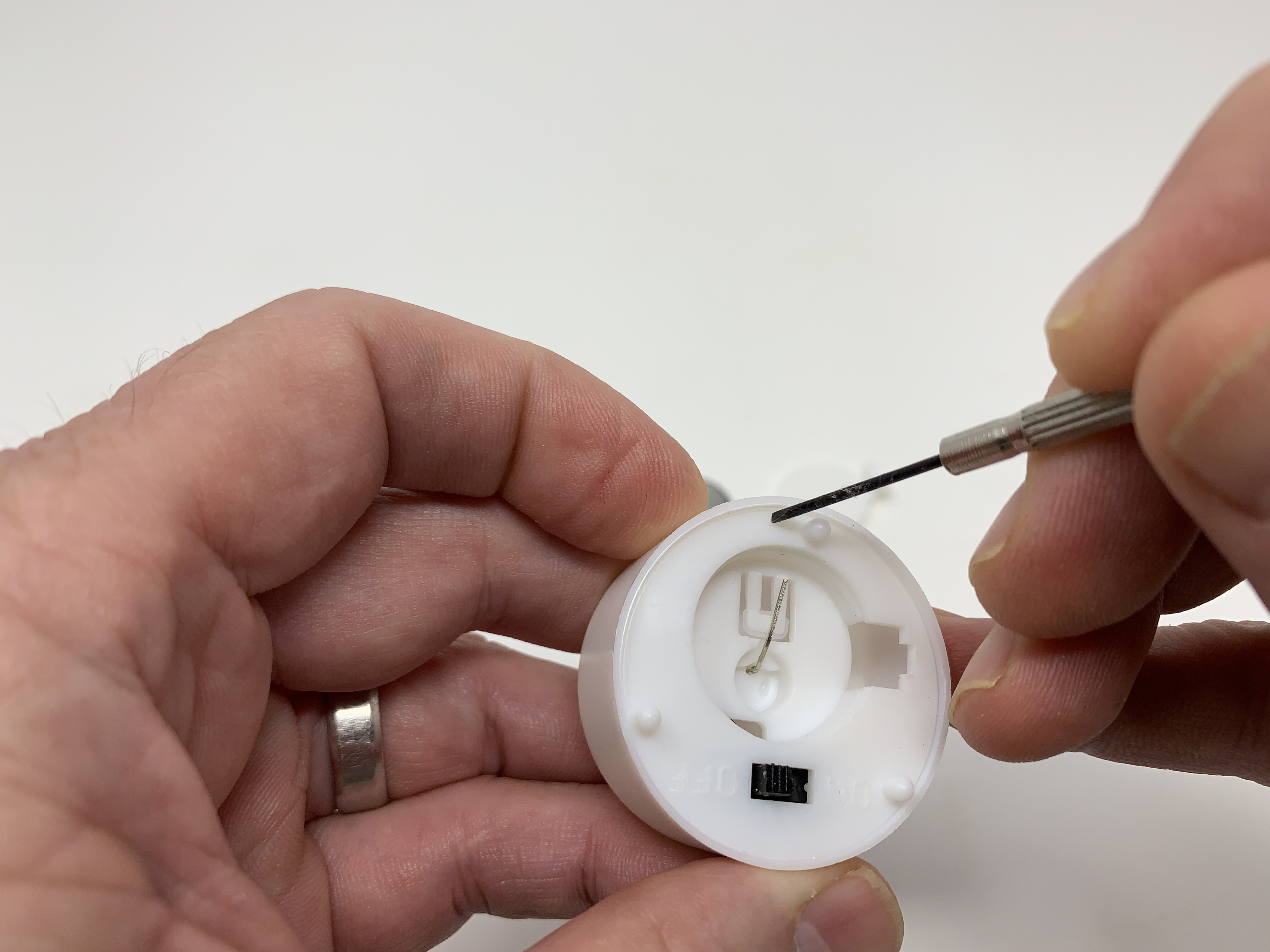
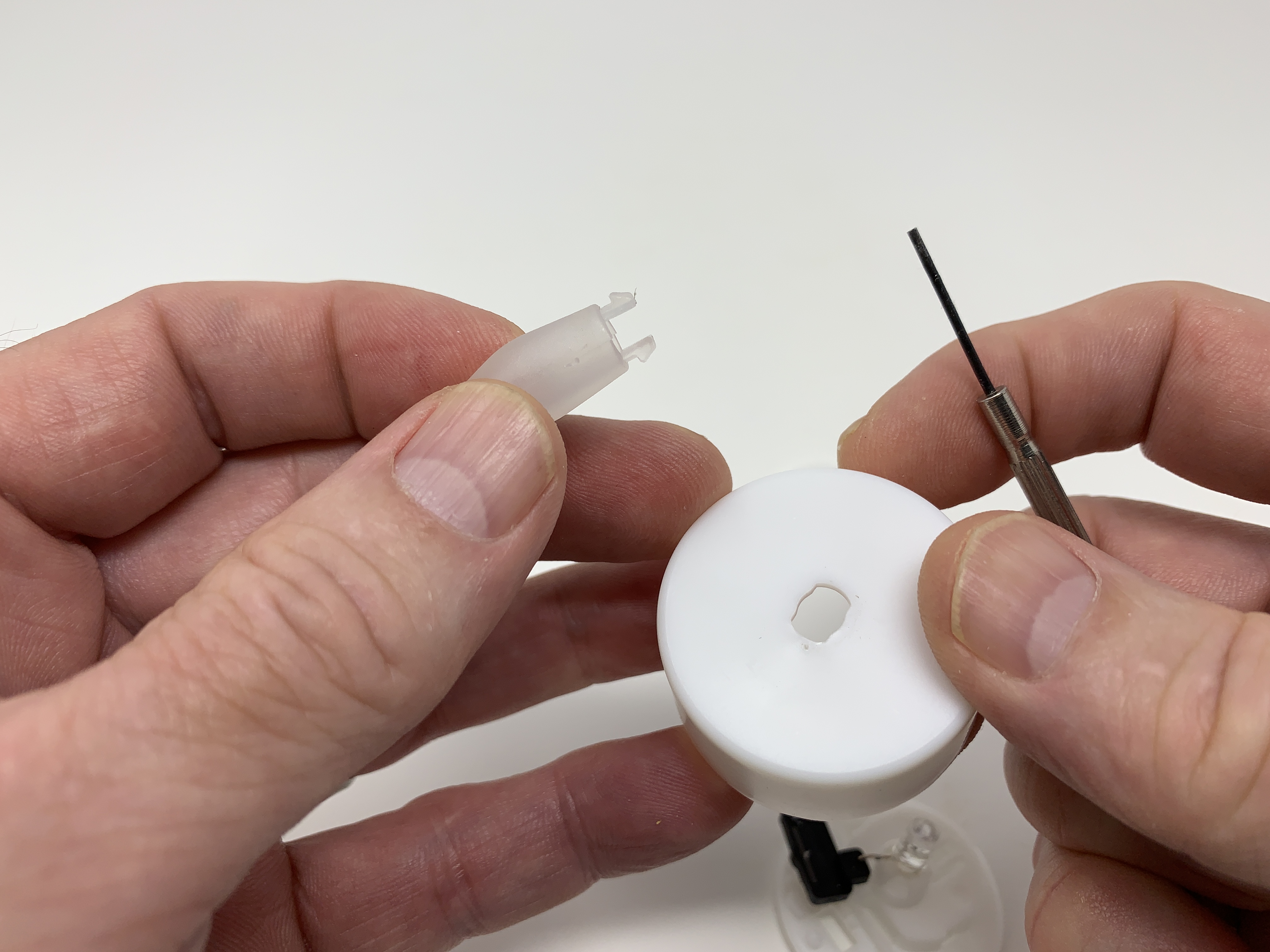
The model uses the flickering LED and the flame lens from the tea lamp I salvaged. To obtain these parts, disassembly of the tea lamp is required. To disassemble the tea lamp, I performed the following steps:
• Removed the battery cover and battery from the tea lamp.
• Used a small screwdriver to remove the cover from tea lamp.
• Used a small screwdriver to remove the lens from the tea lamp cover.
• Removed the LED and switch from the tea lamp base.
• Removed the switch from the LED.
Assemble the Skeleton.
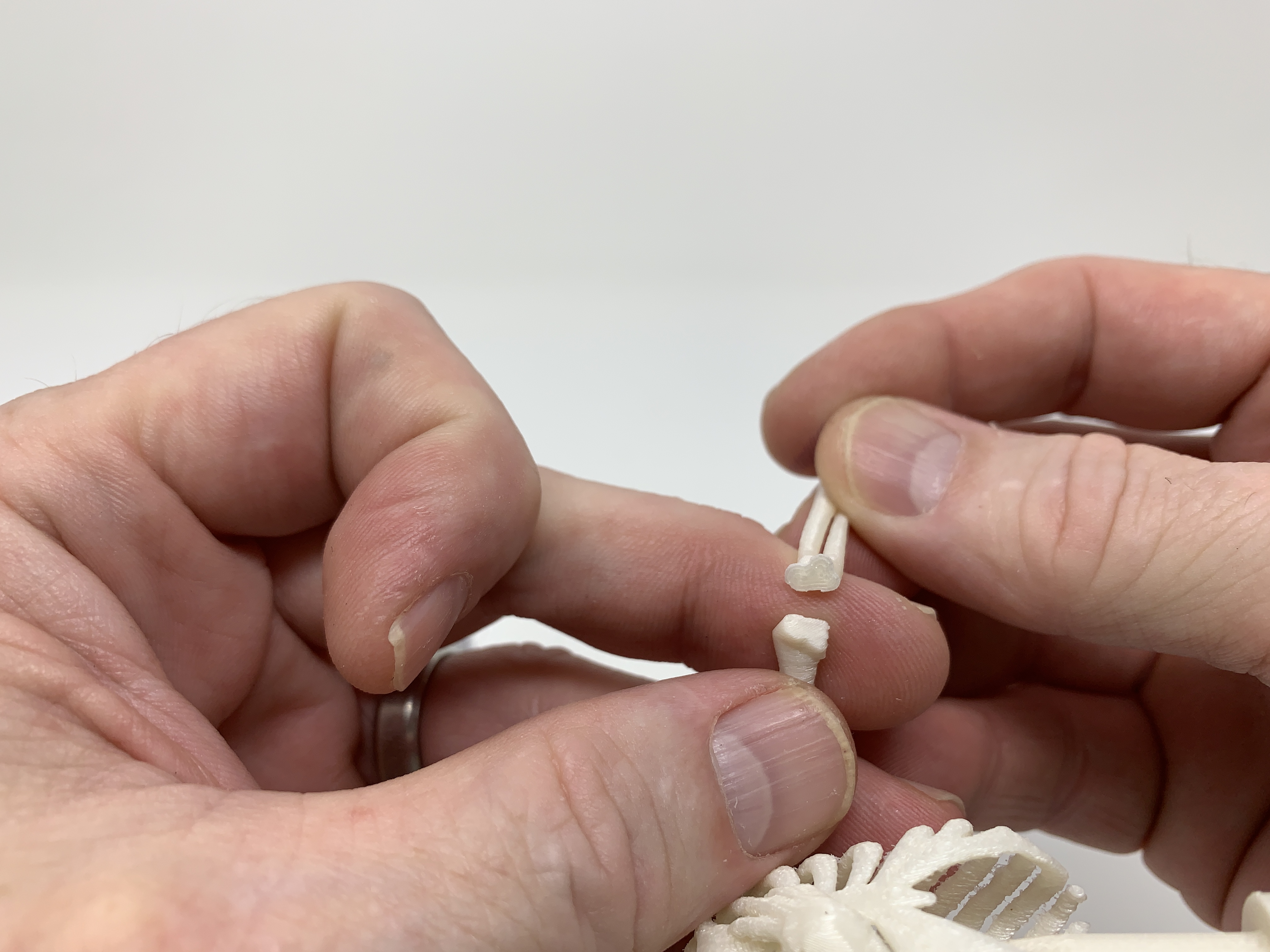
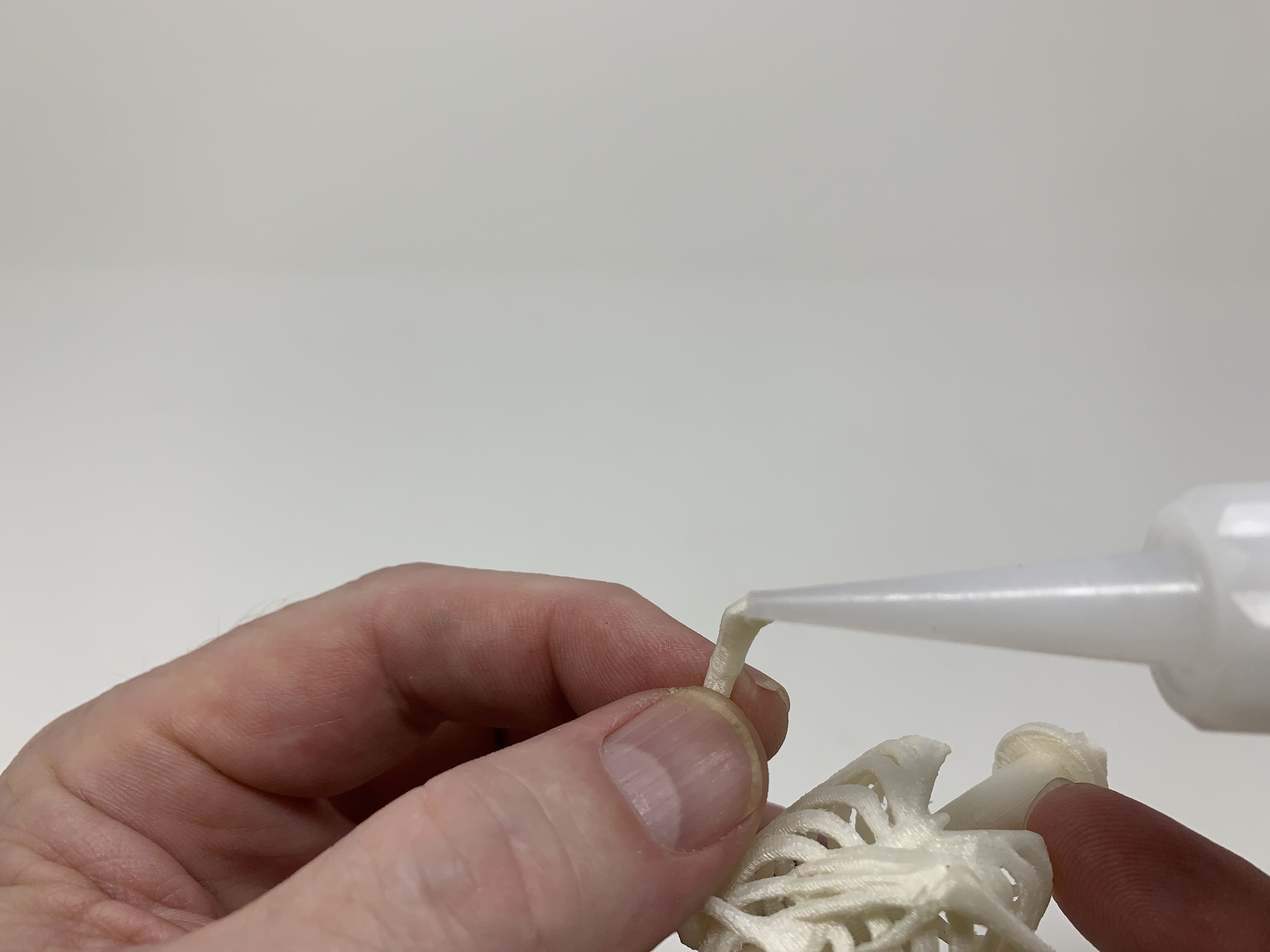
To assemble the skeleton, I aligned "Skeleton, Forearm, Left.stl" with "Skeleton.stl" and secured in place with very small dots of thick cyanoacrylate glue. After curing, I reenforced the joint with more thick cyanoacrylate glue.
Depending on on your printer, your printer settings and the colors you chose, you may wish to reenforce the entire left arm with thin cyanoacrylate glue for additional strength.
Assemble the Base.
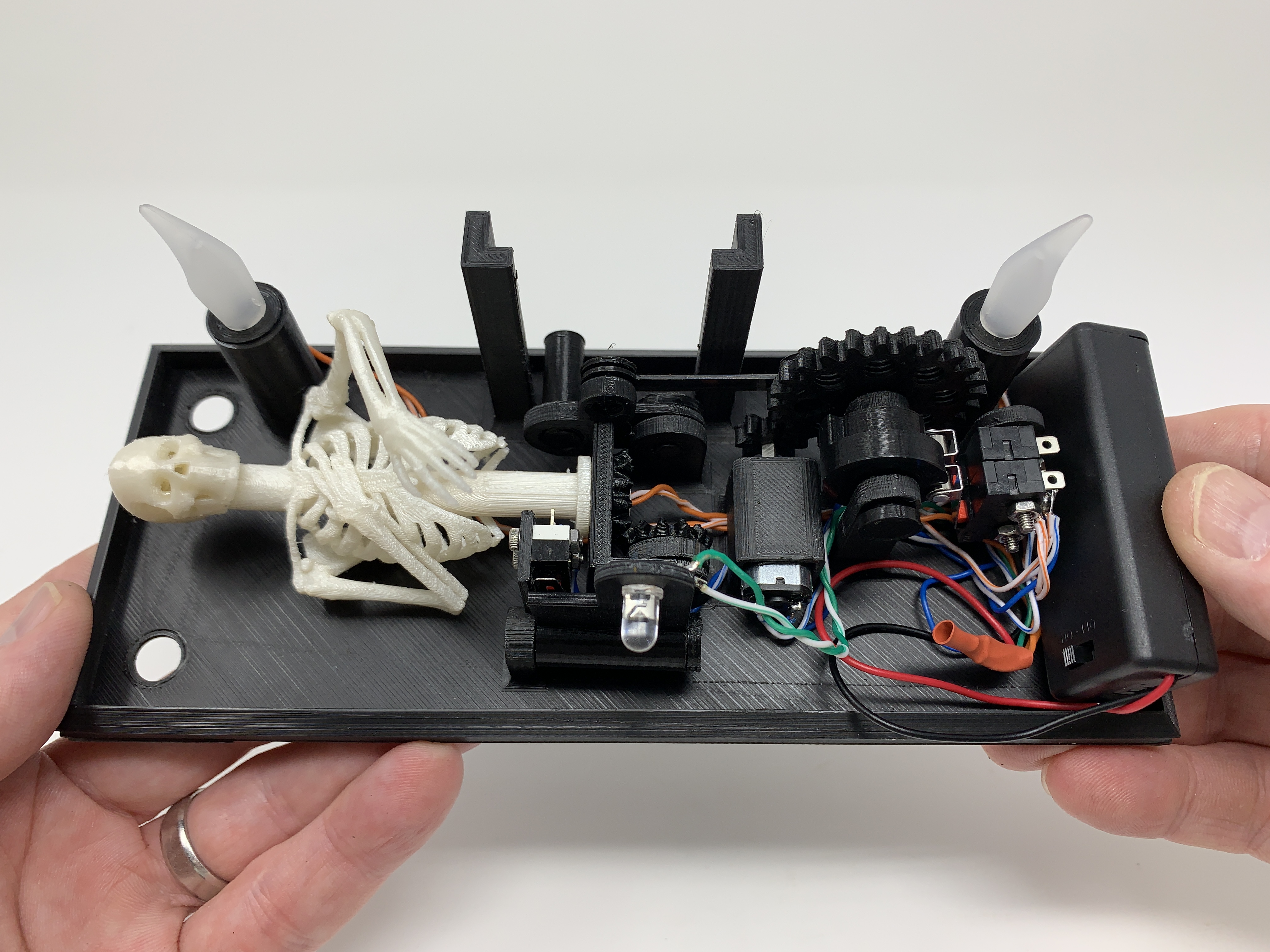
To assemble the base, I performed the following steps:
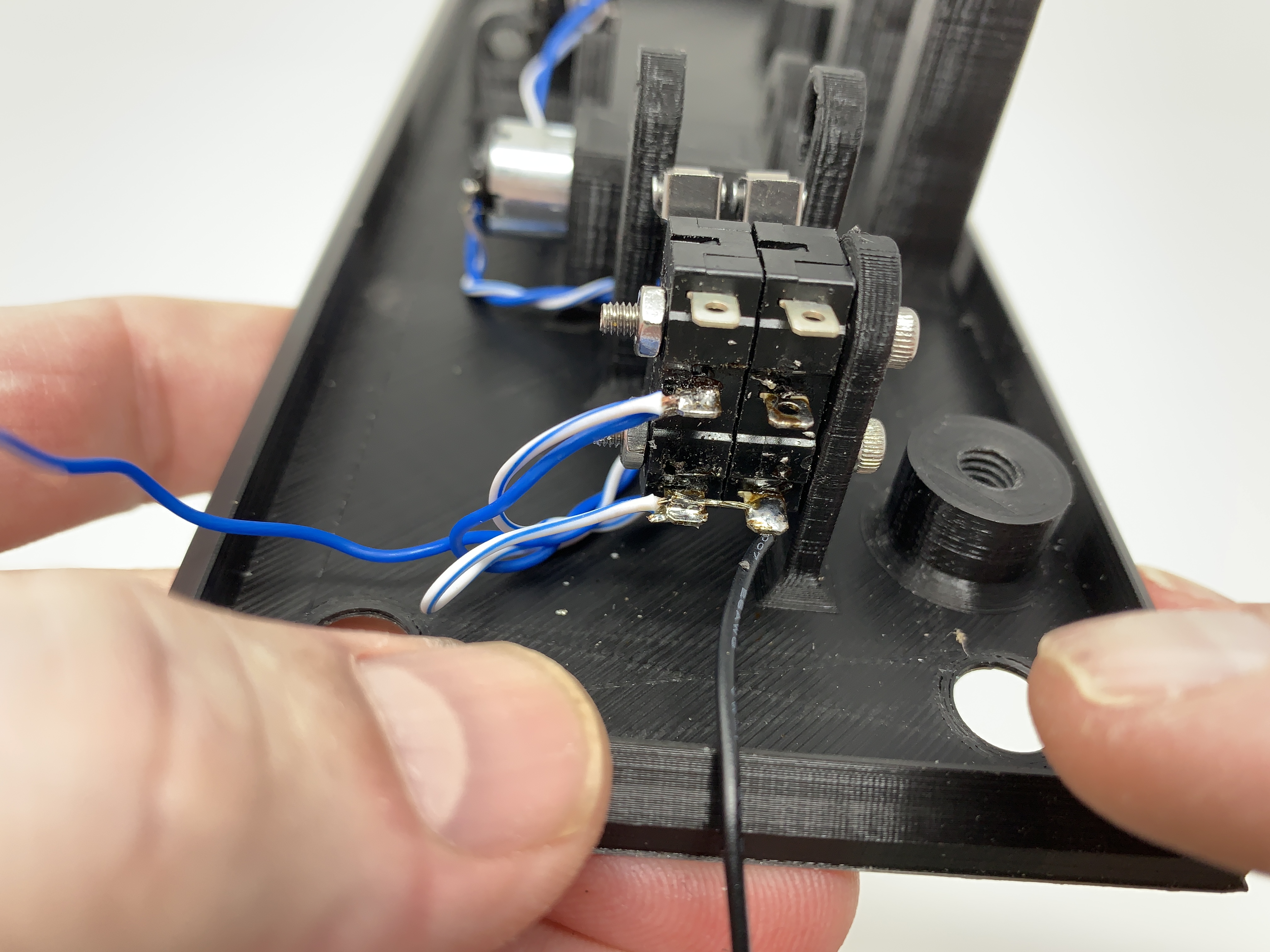
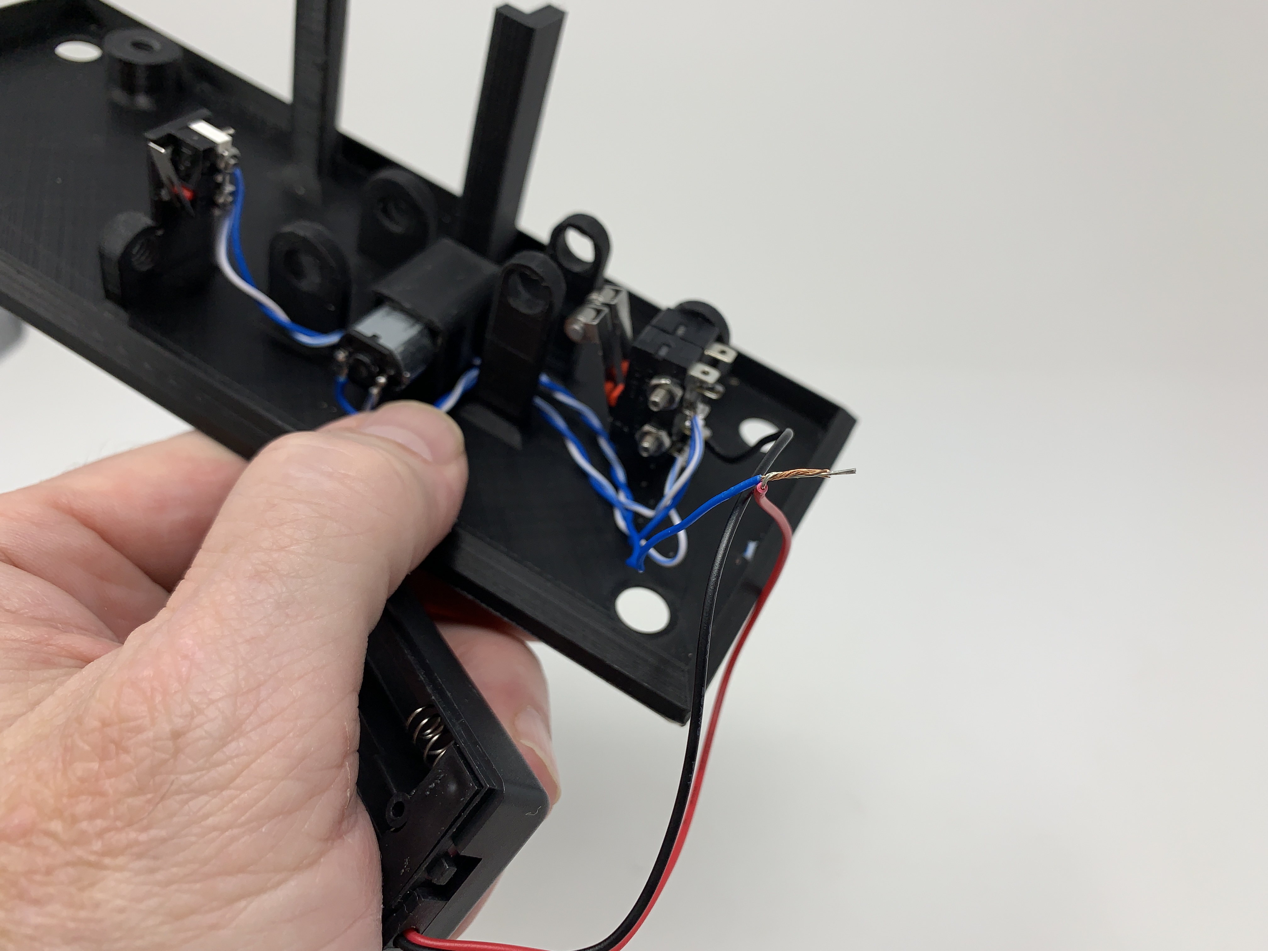
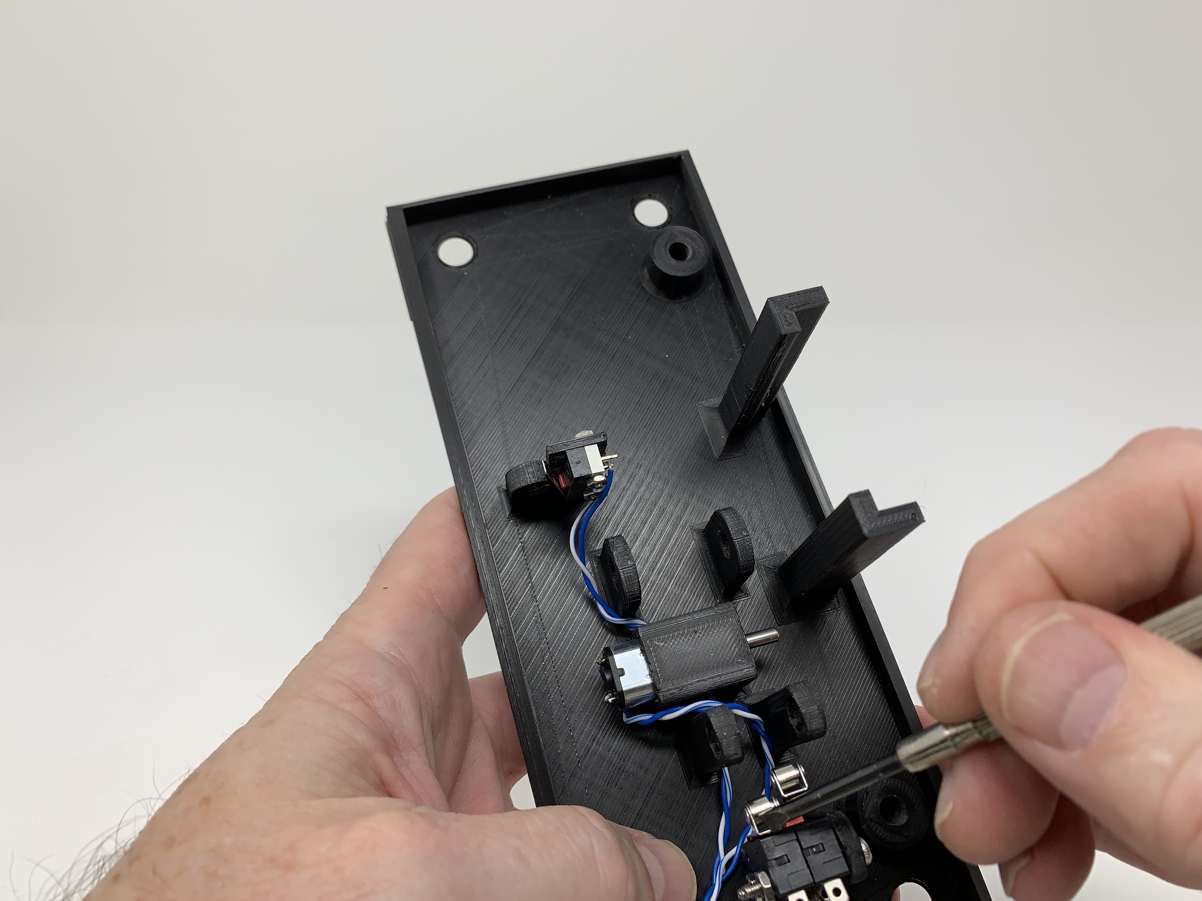
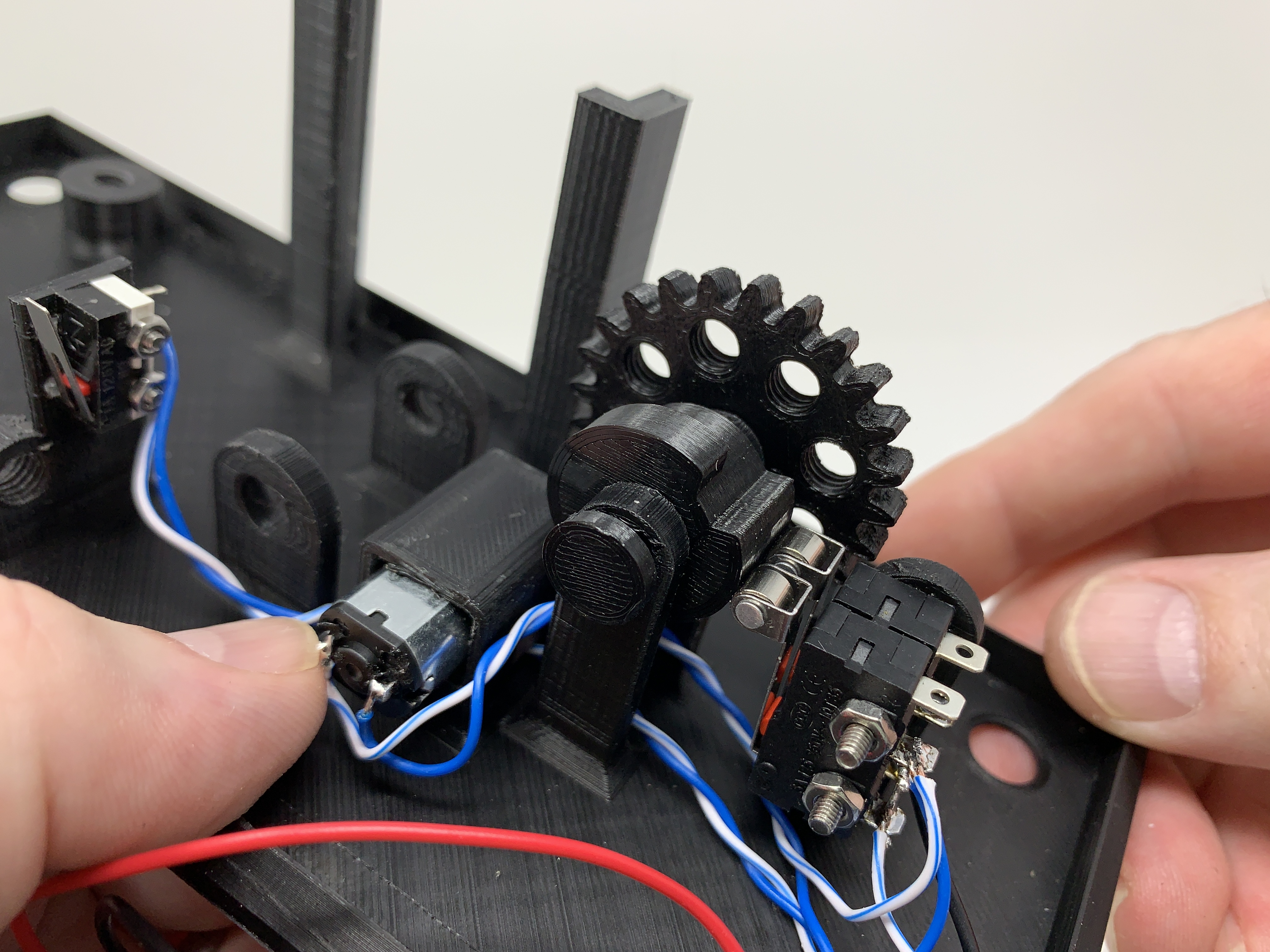
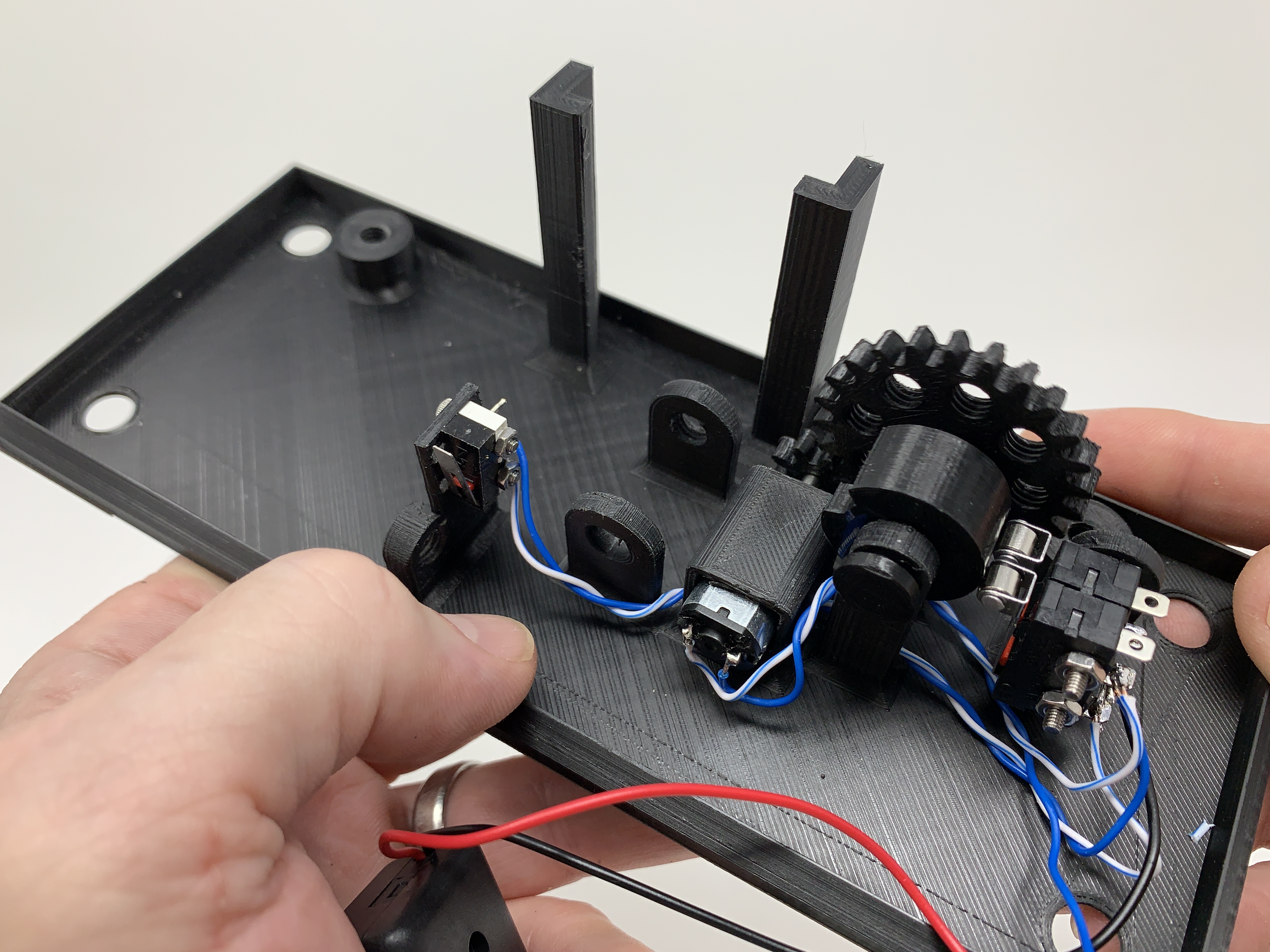
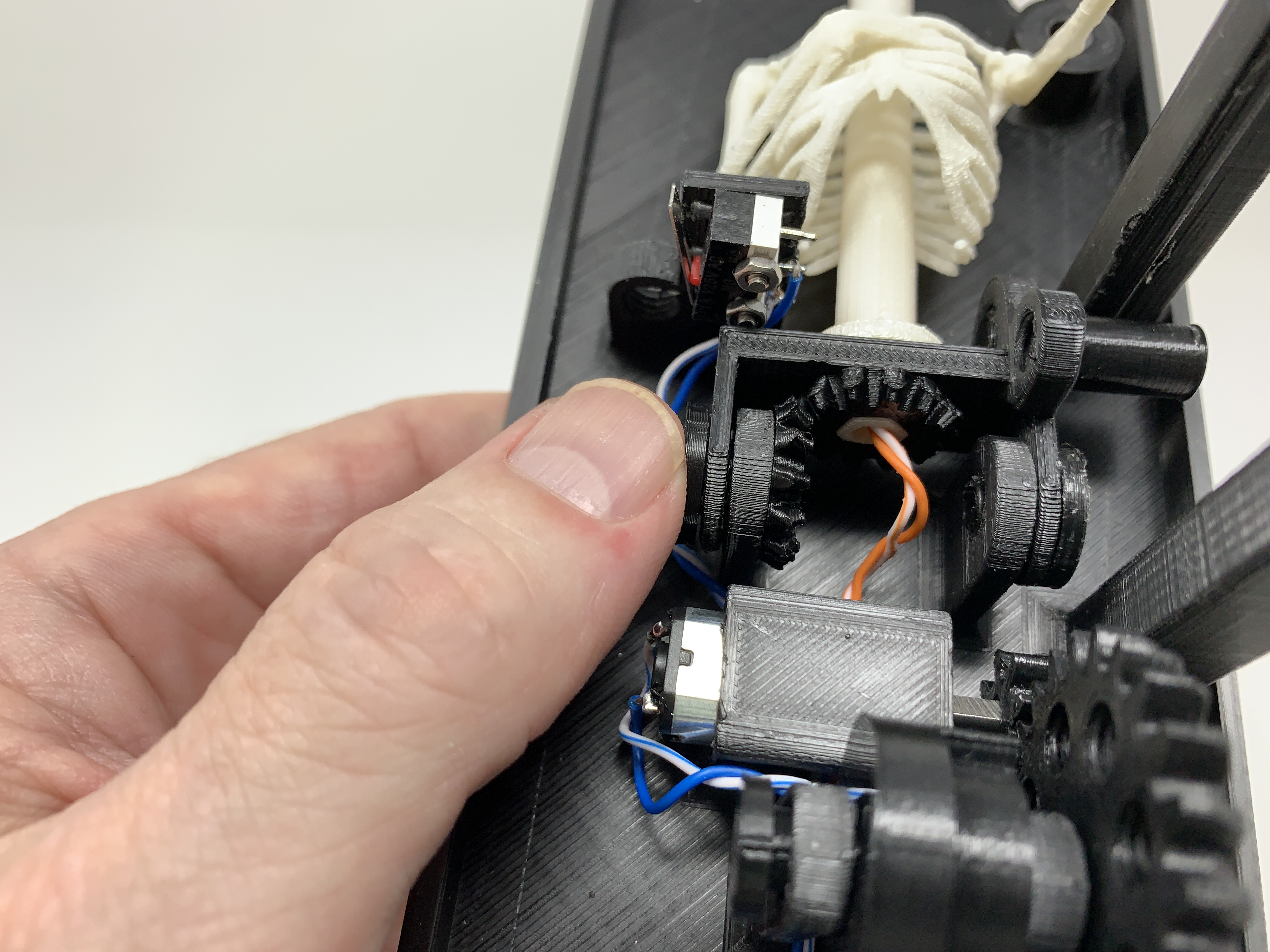
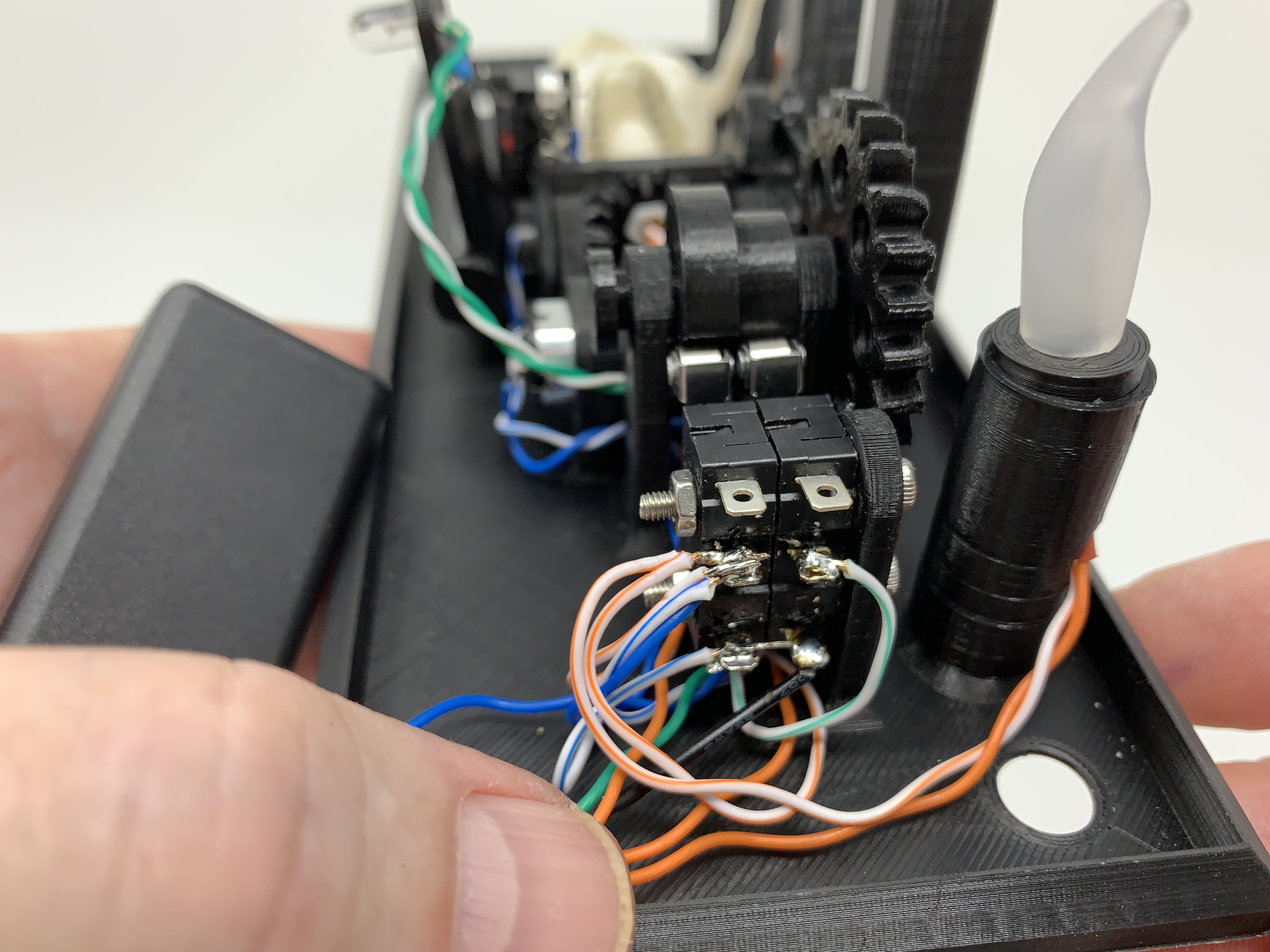
• Attached the push button lever switch (CYT1073) to "Base.stl" using two M2 by 10 bolts and nuts, attached the motor and pushbutton LED roller switches (CYT1096) to the base assembly using two M2.5 by 20 bolts and nuts, and pressed the motor into the motor mount in base assembly.
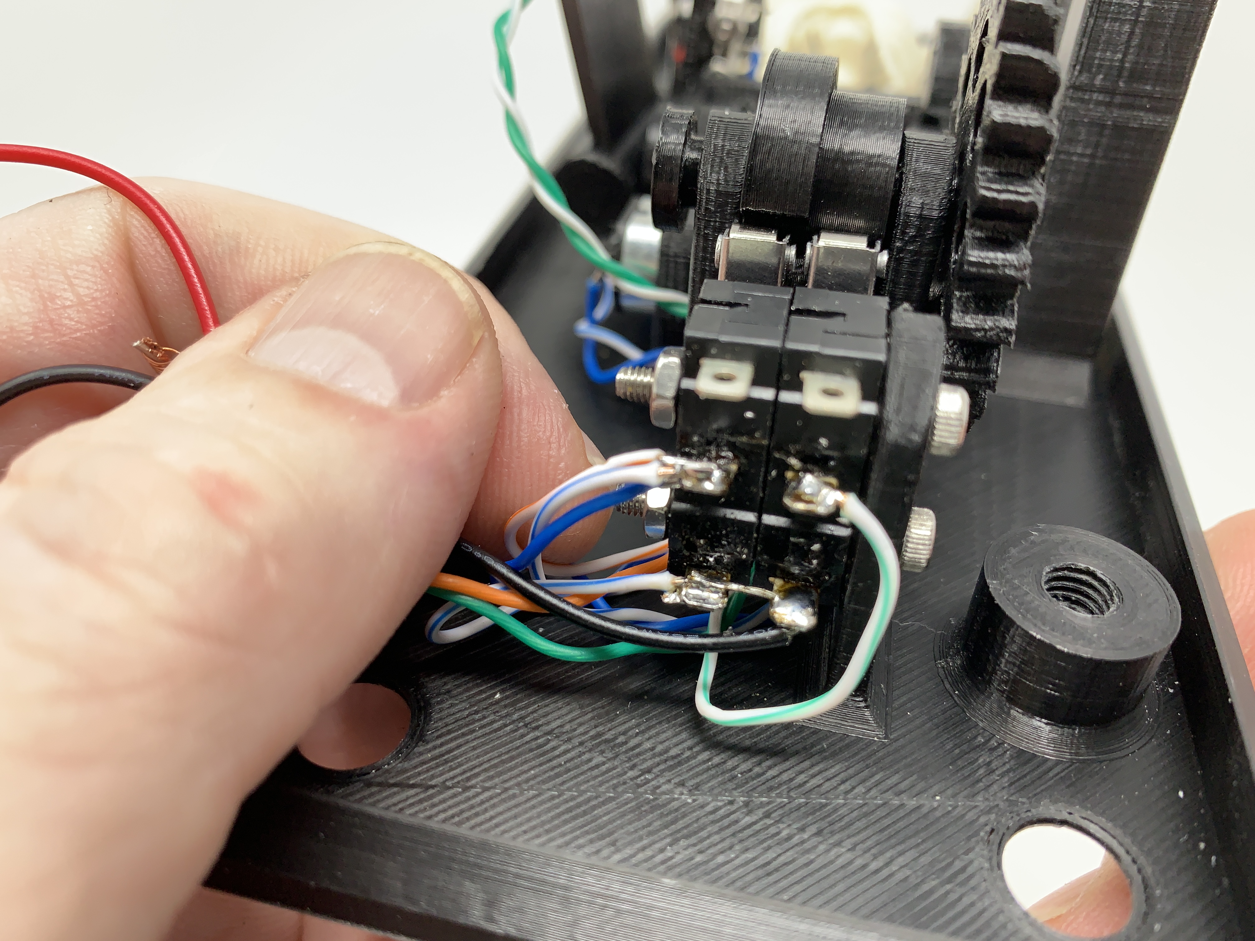
• Soldered a 100mm length of twisted pair blue and white/blue wire to the push button lever switch and routed the wires under the motor mount and out the left side.
• Soldered a 100mm length of twisted pair blue and white/blue wire to the motor "+" and "-" terminals and routed the wires between the camshaft mounts and out the left side.
• Soldered the push button lever switch white/blue wire to terminal 1 of the motor roller switch, then soldered the push button lever switch blue wire to terminal 3 of the motor roller switch.
• Soldered the motor blue/white wire to terminal 3 of the motor roller switch.
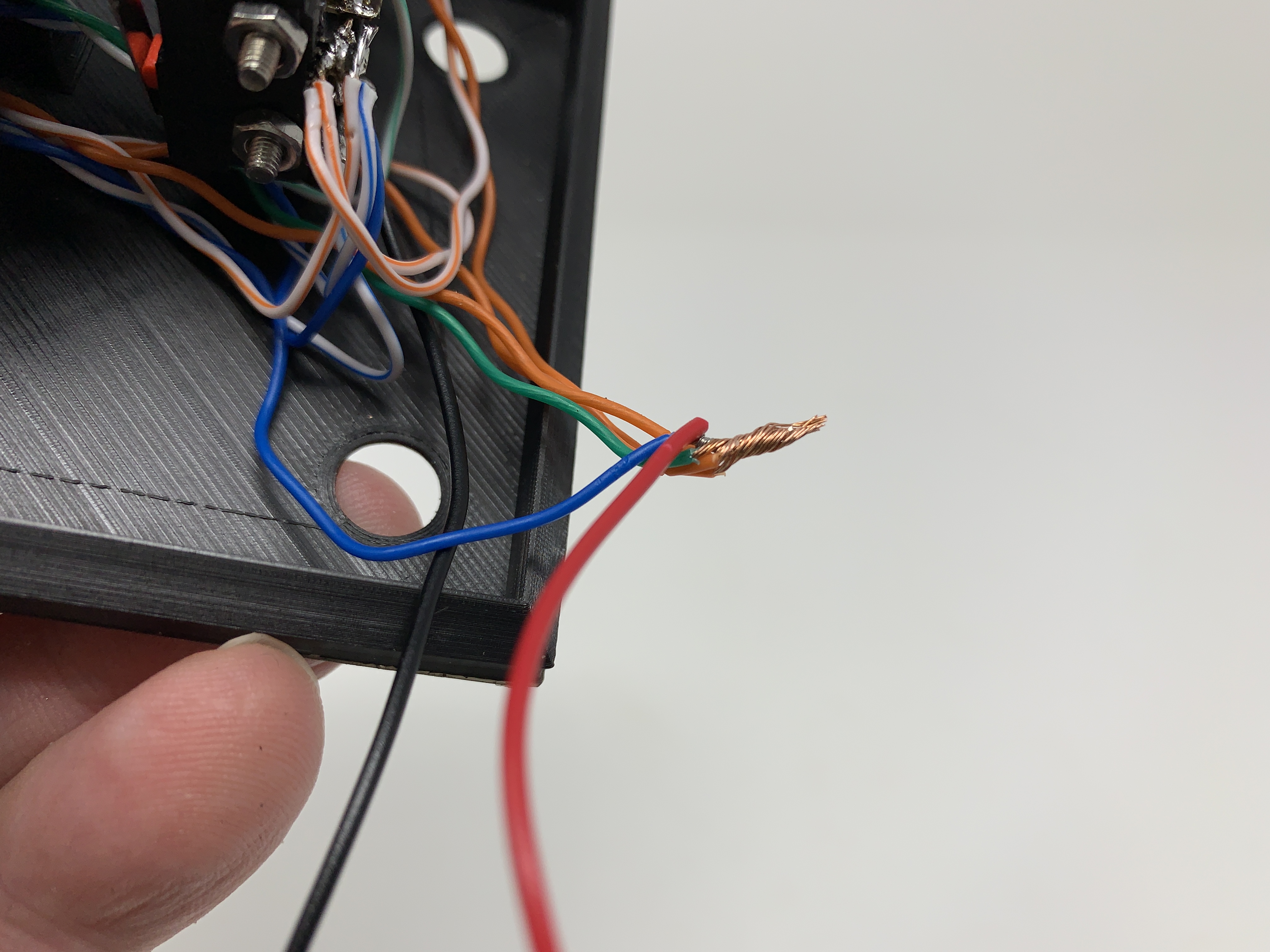
• Soldered the battery holder black wire to terminal 1 of the motor roller switch and pushbutton LED switch.
• Twisted the battery holder red wire and motor blue wire together (more wires will be added later).
• Installed two AAA batteries in the battery back and turned the battery back on/off switch to on.
• Activated the motor roller switch and checked the motor rotation for counter clockwise rotation when viewed from the motor shaft end of the motor. If the motor was not running counter clockwise, I swapped the wires at the motor "+" and "-" terminals.
• Activate the push button lever switch to make sure the motor turned counter clockwise as viewed from the motor shaft end of the motor.
• Turned the battery pack on/off switch to off.
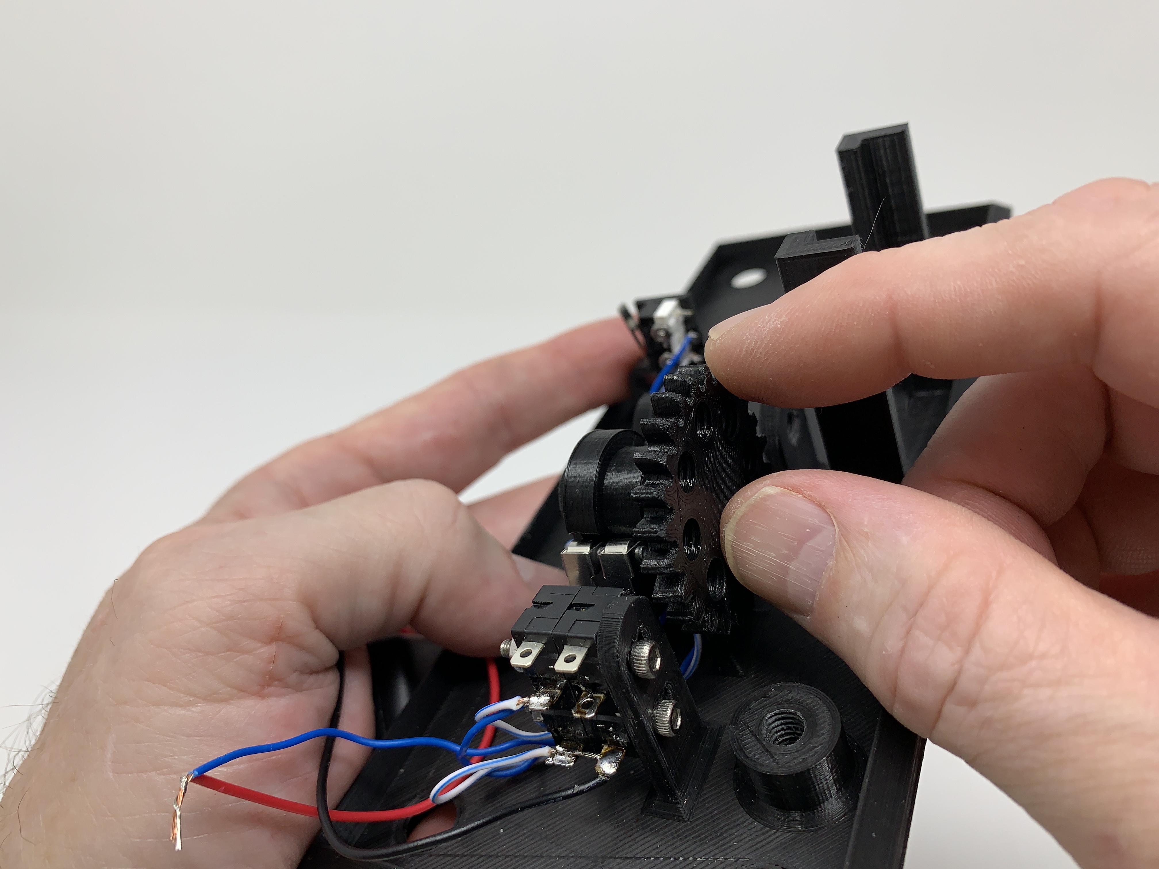
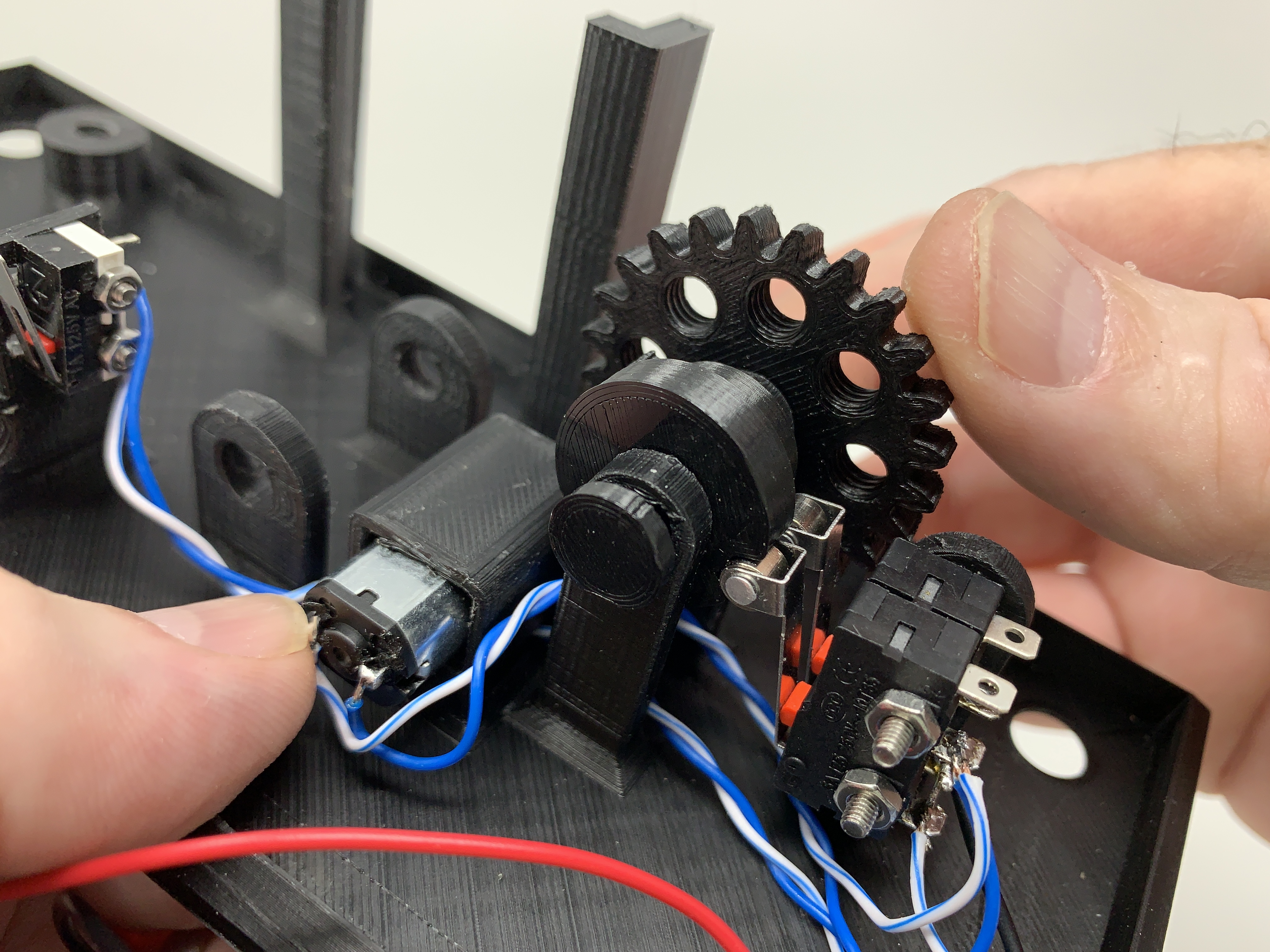
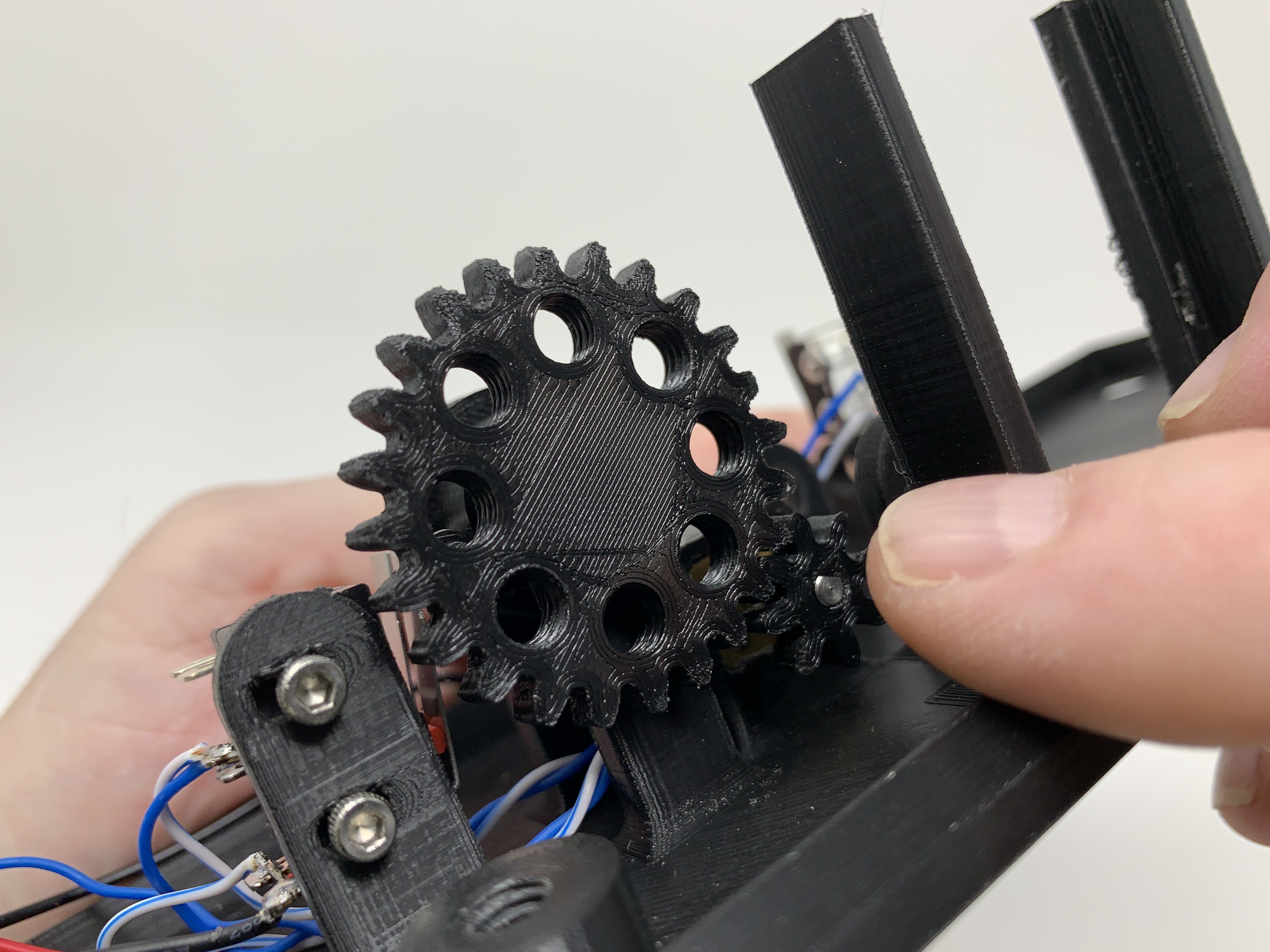
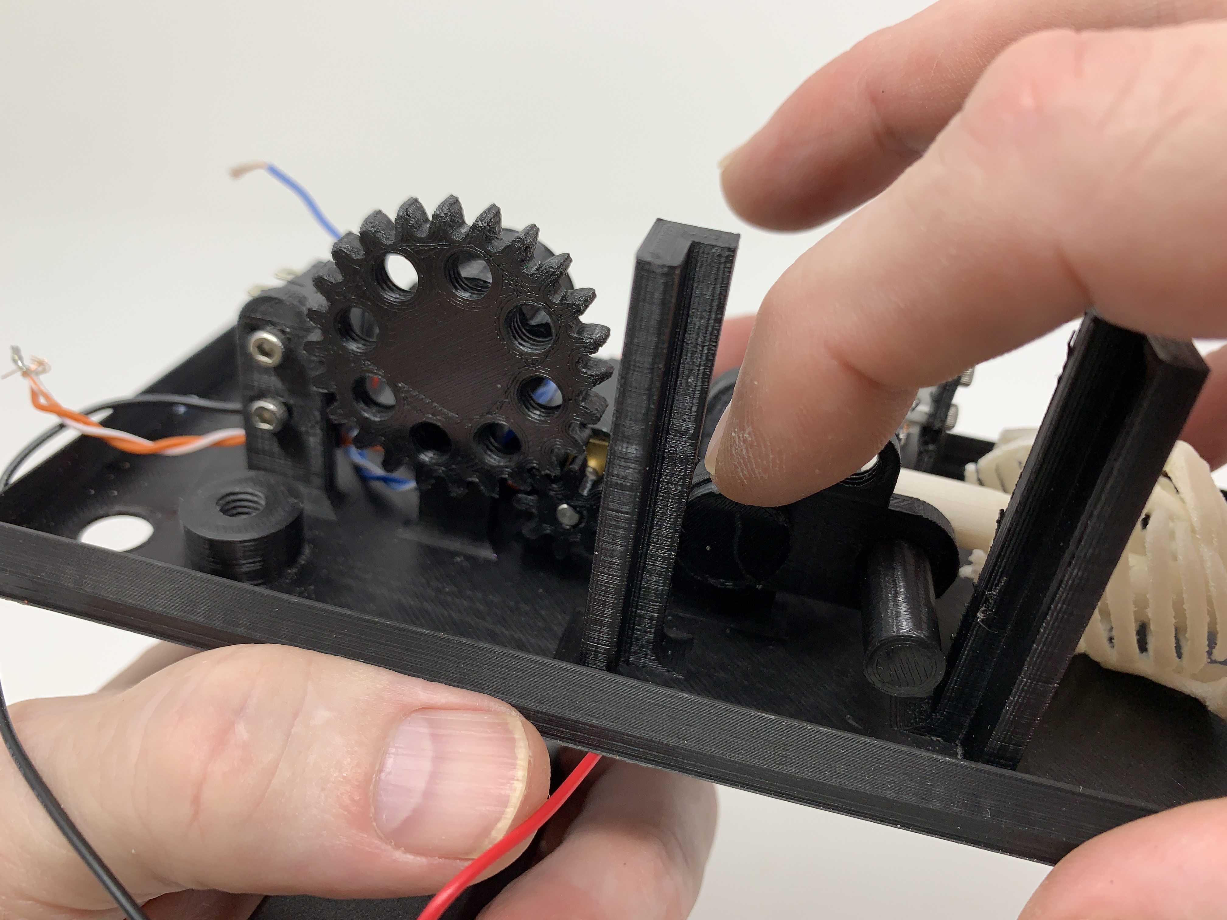
• Positioned "Camshaft.stl" between the camshaft towers in the base assembly then firmly secured in place by threading "Gear, Camshaft.stl" to the camshaft from the rear camshaft tower and "Axle, Camshaft.stl" to the camshaft from the front camshaft tower.
• Pressed "Gear, Motor.stl" onto the motor shaft and aligned the motor and gear assembly with "Gear, Camshaft.stl".
• Turned the battery pack on/off switch to on.
• Activated the push button switch and made sure the camshaft rotated 360 degrees then stopped in the off position. If not, I adjusted the position of the motor and LED pushbutton roller switches.
• Turned the battery pack on/off switch to off.
• Made sure the camshaft was in the off position.
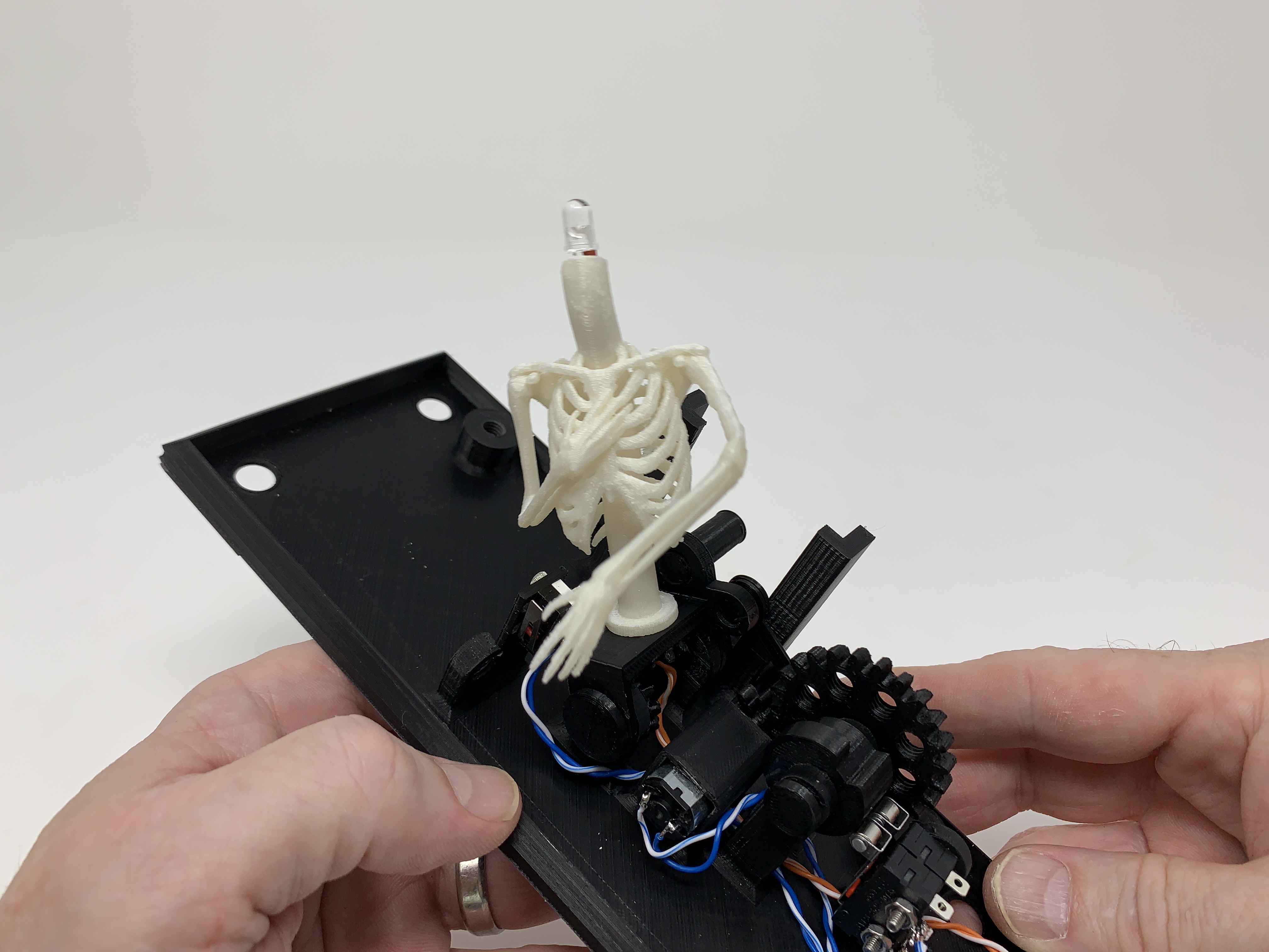
Add the Skeleton to the Base.
To add the skeleton to the base, I performed the following steps:
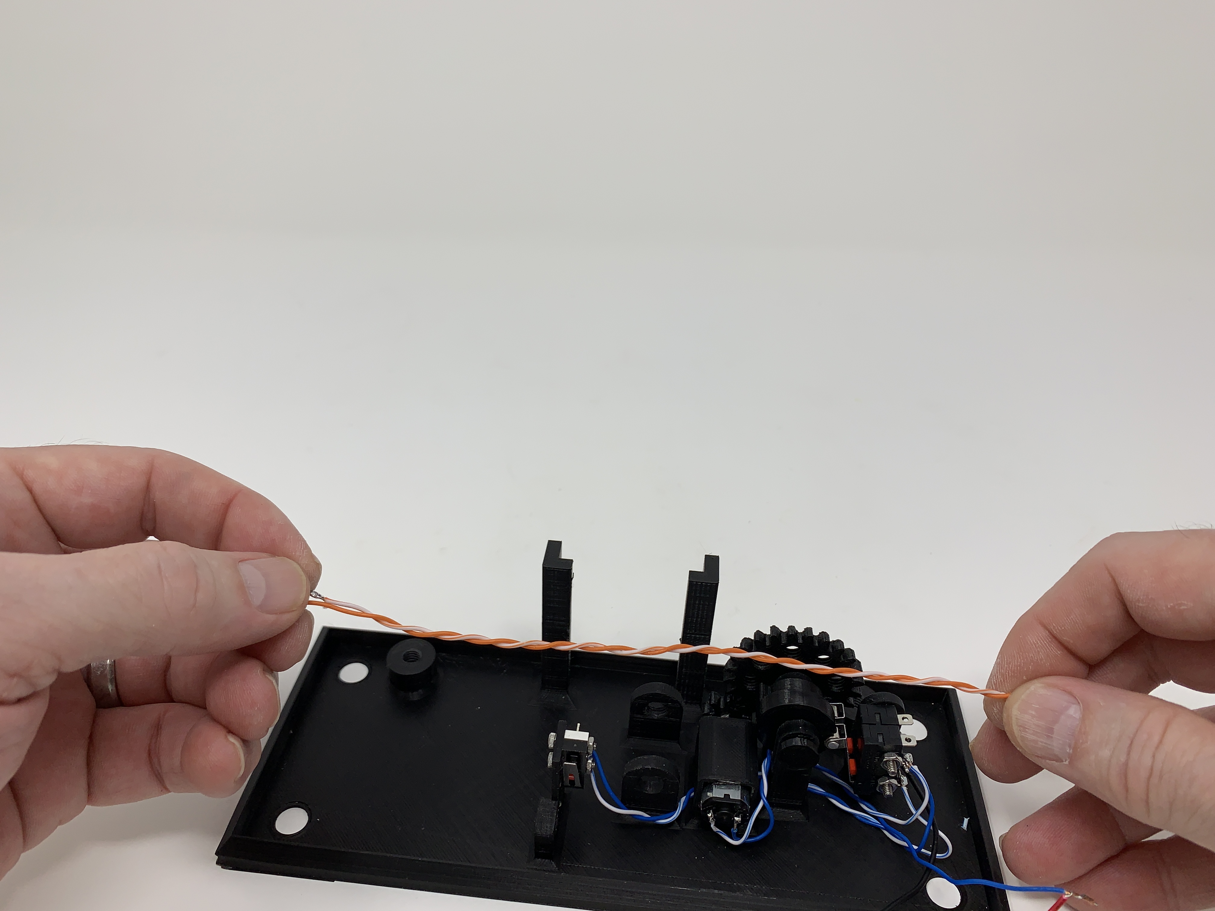
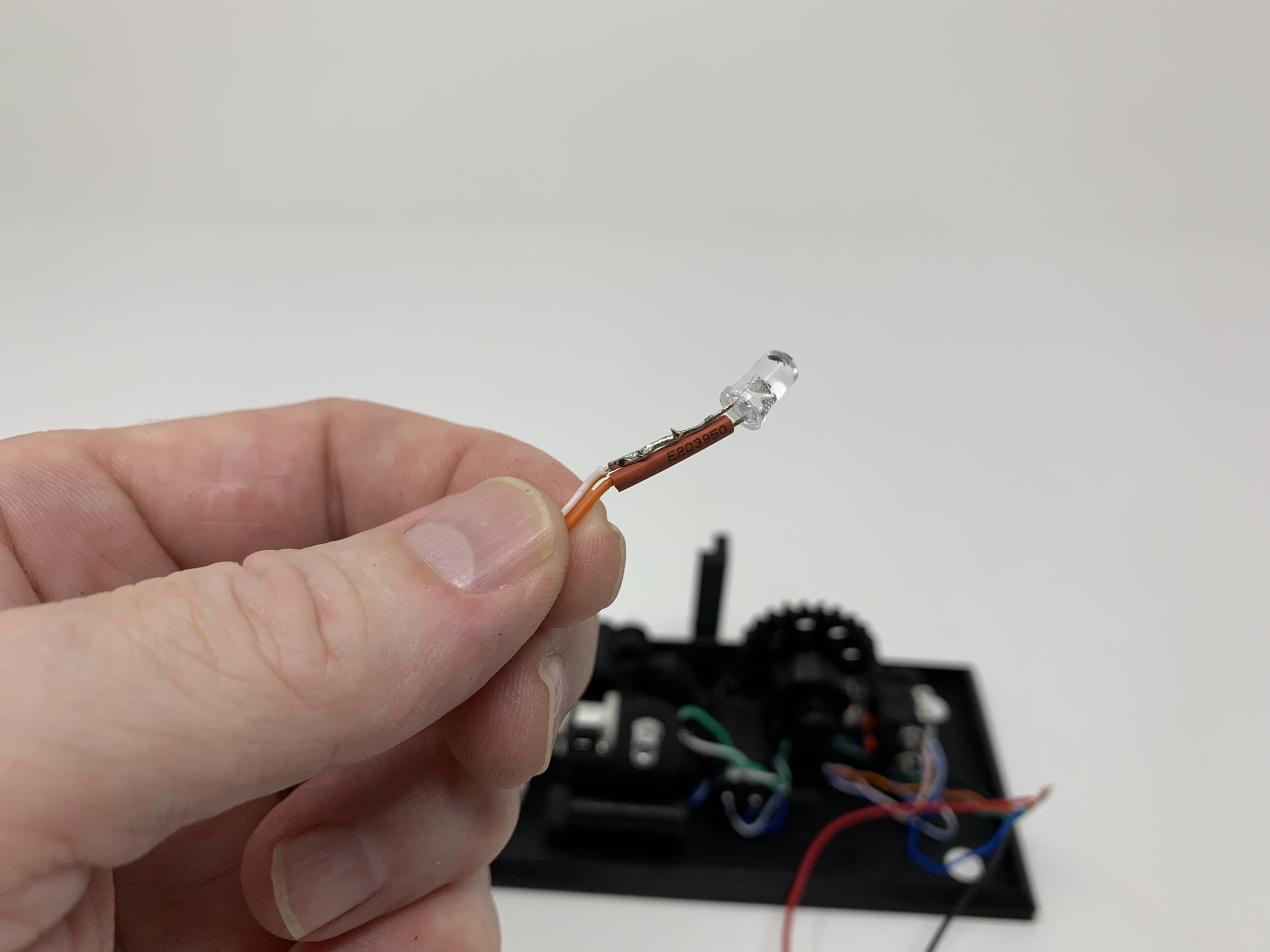
• Cut a 180mm length of orange and white/orange twisted pair wire.
• Soldered a 100ohm resistor to the cathode lead of one of the 3mm LEDs,
• Soldered the white/orange lead to the free end of the 100omh resistor.
• Soldered the orange lead to the anode lead of the 3mm LED and insulated with heat shrink tubing.
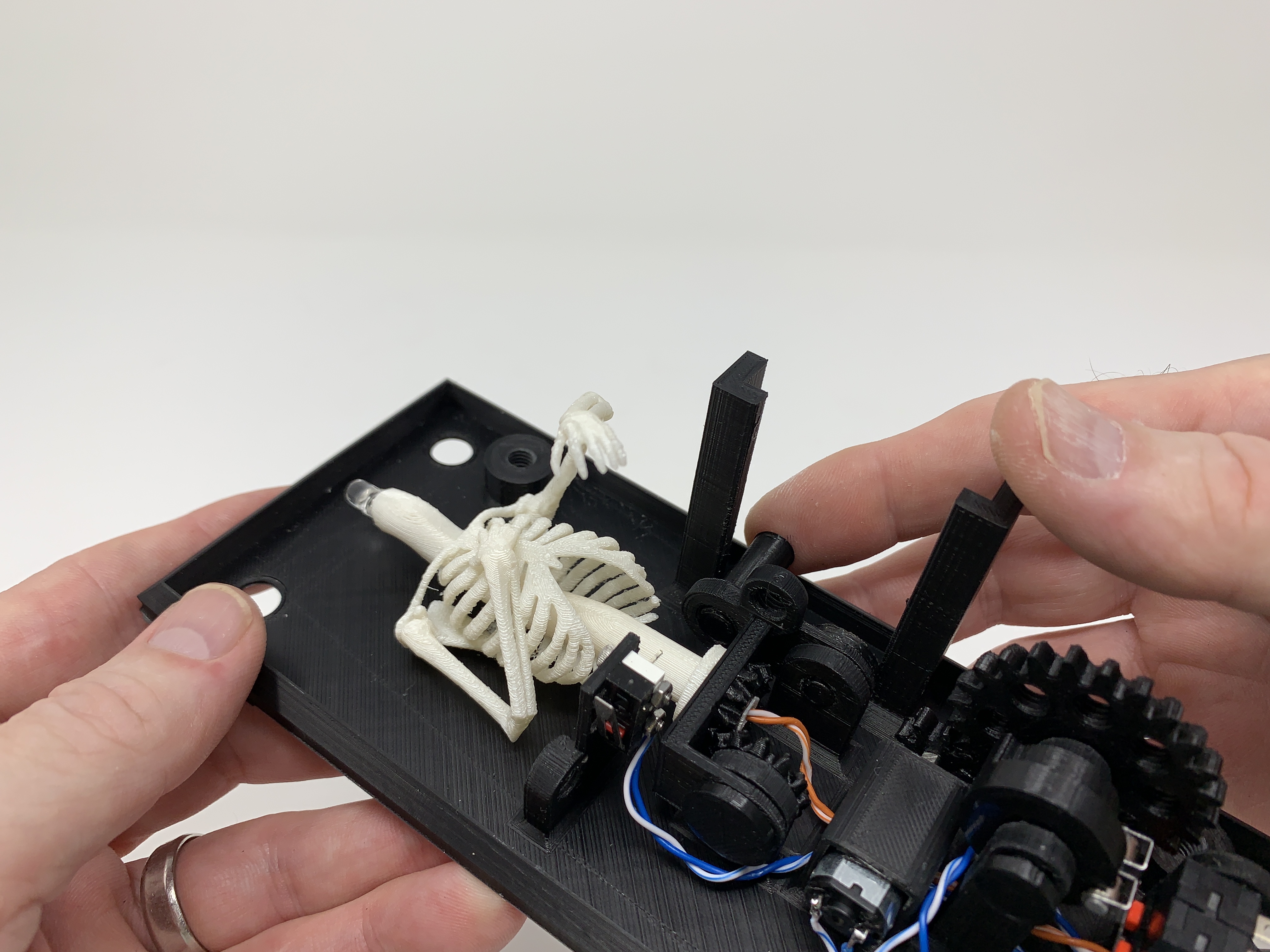
• Slid the free ends of the wiring down the spine of "Skeleton.stl".
• Threaded "Pin, Mount, Skeleton.stl" into "Mount, Skeleton.stl".
• Threaded the skeleton head LED wiring through the skeleton mount, through "Gear, Crown, Axle.stl" (flat side first), under the motor mount and out the left side.
• Pressed "Gear, Crown, Axle.stl" onto the hexagonal shaft on the skeleton such that the skeleton rotated smoothly on the mount but not loose. When properly adjusted, a small dot of thick cyanoacrylate glue may be required to secure the gear on the skeleton.
• Placed the mount onto the base surrounding the mount towers.
• Threaded "Axle, Mount, Skelton.stl" through the rear mount tower and the mount assembly then into the base assembly.
• With the skelton in the full down position, positioned "Gear, Crown, Base.stl" on the inner surface of the front mount tower and secured in place by threading "Axle, Gear, Crown, Mount, Skeleton.stl" through the mount assembly then into the gear. This gear must remain in place without rotating.
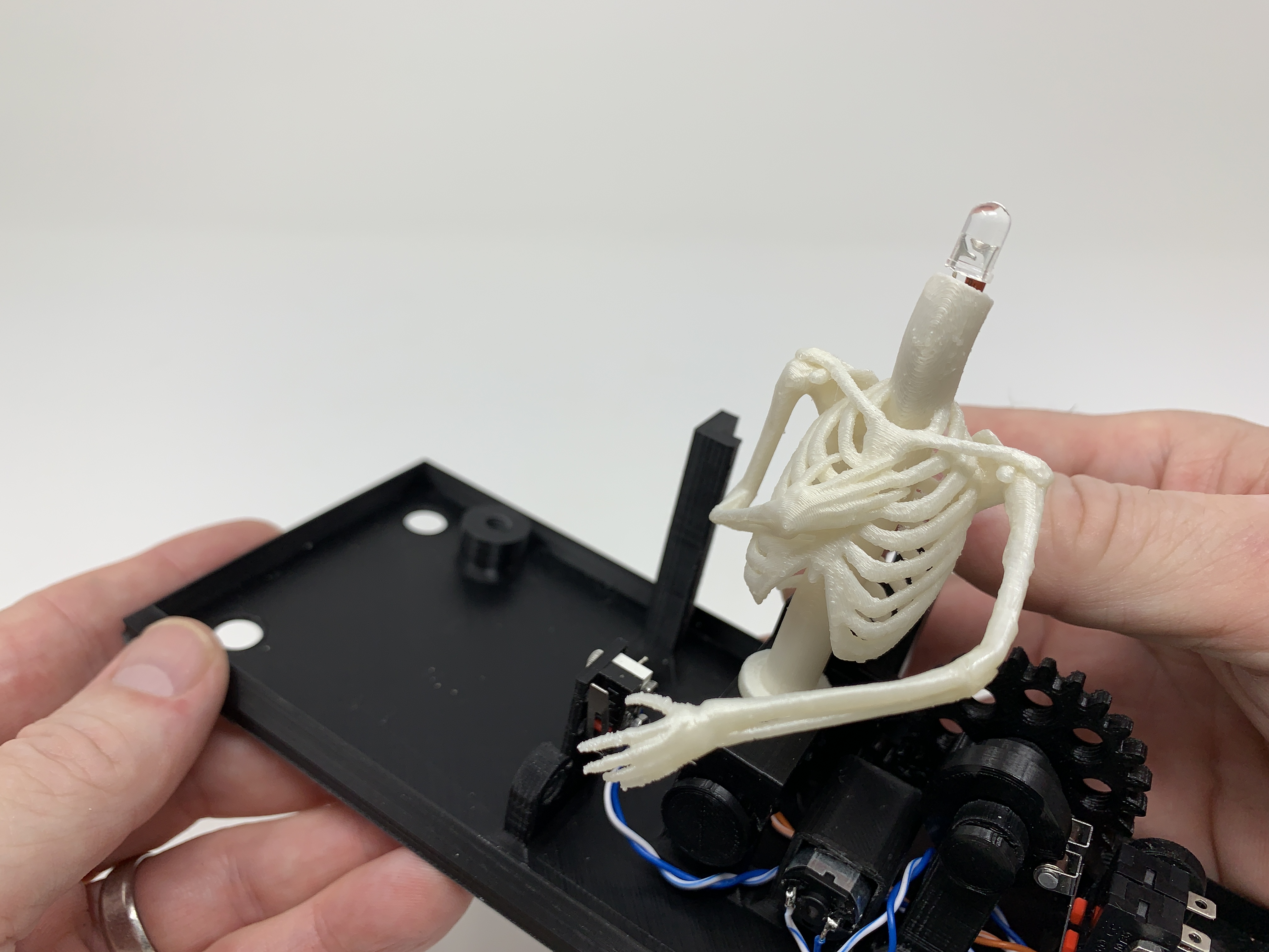
• Checked for free and proper movement of the skeleton by lifting and lowering the assembly using "Pin, Mount, Skeleton.stl".
• With the skelton in the full down position and the camshaft in the off position, attached "Arm.stl" to "Gear, Camshaft.stl" in the camshaft gear hole closest to the arm mounting hole in the skeleton mount assembly, using one "Axle, Arm.stl".
• Attached the remaining end of "Arm.stl" to the skeleton mount assembly using the remaining "Axle, Arm.stl".
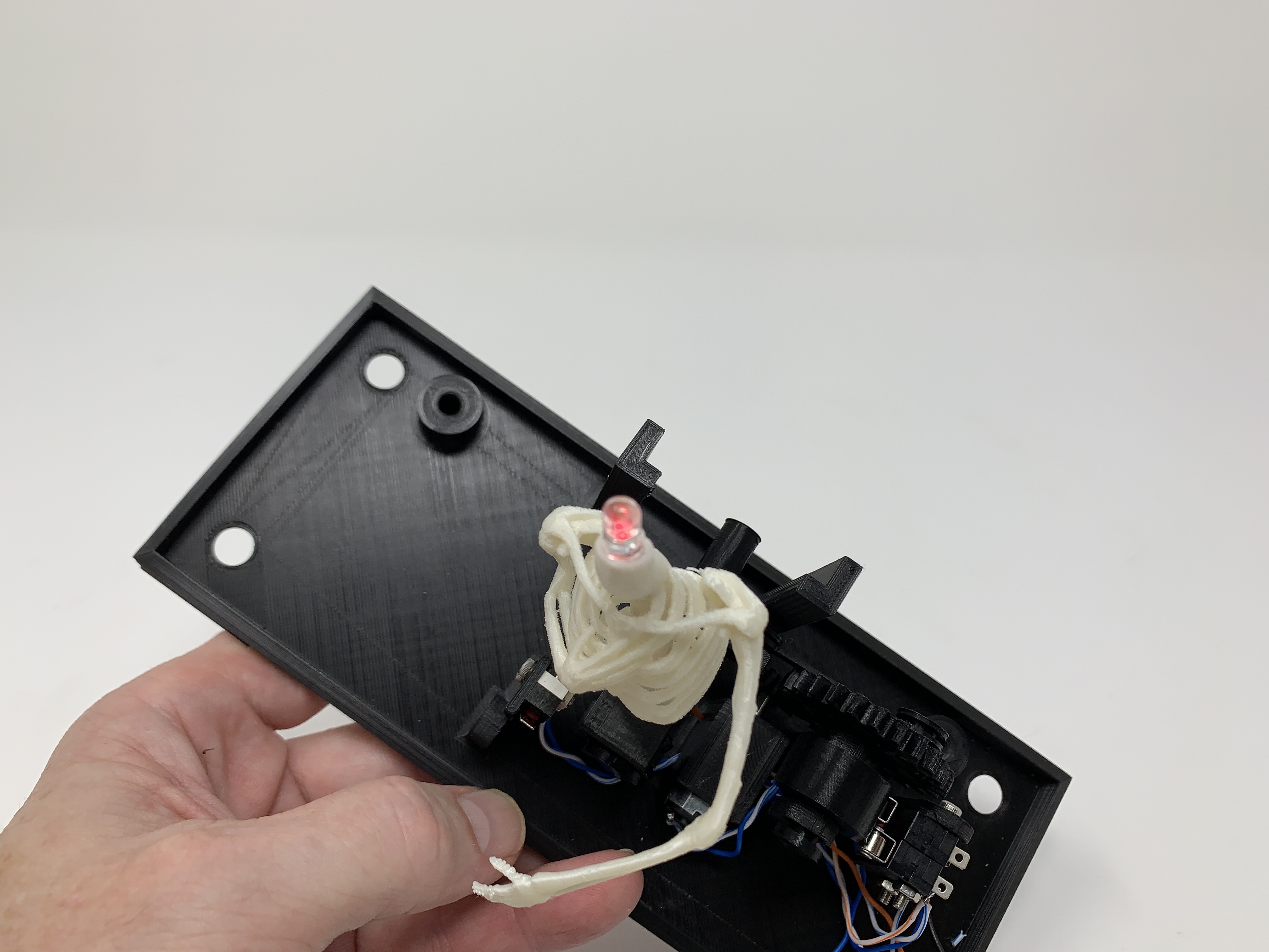
• Checked to make sure the camshaft was in the off position and the skeleton was in the full down position.
• Soldered the white/orange wire from the head LED to the motor roller switch terminal 3.
• Twisted the orange wire from the head LED to the previously twisted battery holder red wire (more wires will be added later).
• Turned the battery holder switch on.
• Pressed the push button lever switch to make sure the skeleton rose, rotated, and lowered without strain or binding, and the head LED illuminated during the entire cycle.
• Turned the battery pack on/off switch to off.
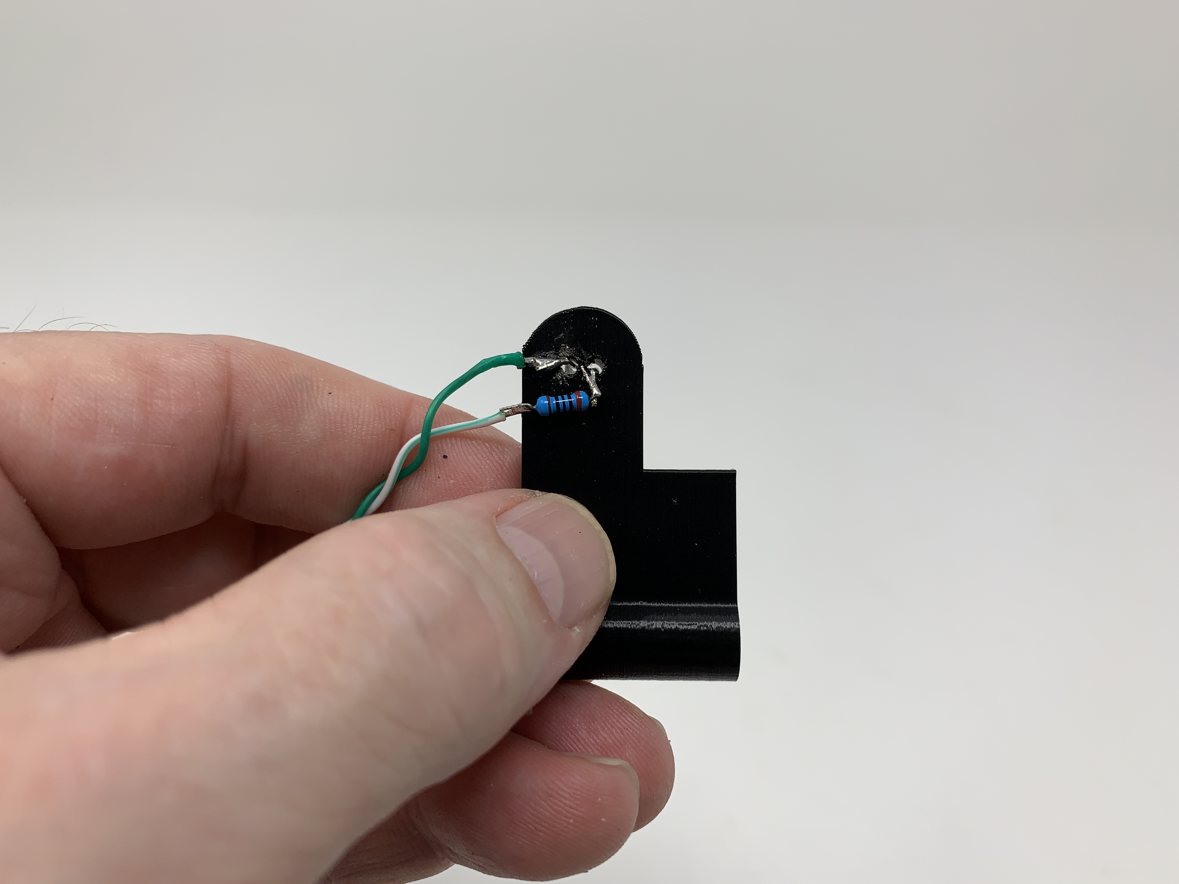
Add the Pushbutton Lever to the Base.
To add the push button lever to the base, I performed the following steps:
• Cut a 150mm length of green and white/green twisted pair wire.
• Positioned the remaining 3mm LED through the holes in "Lever, Pushbutton.stl".
• Soldered the green wire to the LED anode lead.
• Soldered a 100ohm resistor to the LED cathode lead.
• Solderer the white/green wire to the free end of the 100ohm resistor.
• Applied small dots of cyanoacrylate glue to secure the wires and resistor in place.
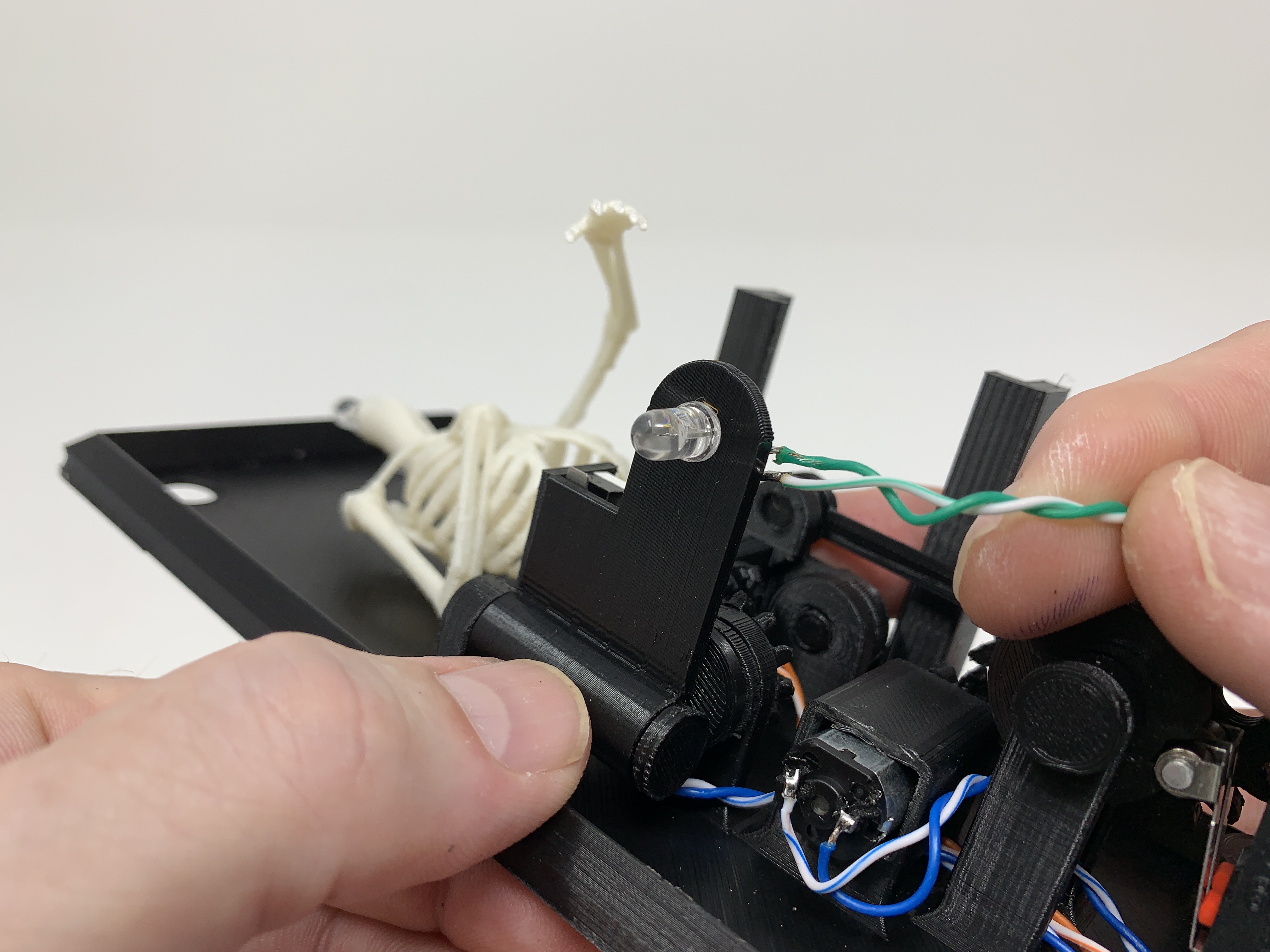
• Positioned the pushbutton lever assembly in place on the base assembly and secured in place with "Axle, Lever, Pushbutton.stl".
• Routed the wires under the camshaft and out the left side.
• Soldered the white/green wire to terminal 3 of the pushbutton LED roller switch.
• Twisted the green wire to the previously twisted battery holder red wire (more wires will be added later).
• Turned the battery holder on/off switch to on.
• Pressed the pushbutton lever assembly and made sure the mechanism cycled and the pushbutton LED illuminated from the start of the cycle then extinguished halfway through the cycle.
• Turned the battery holder on/off switch to off.
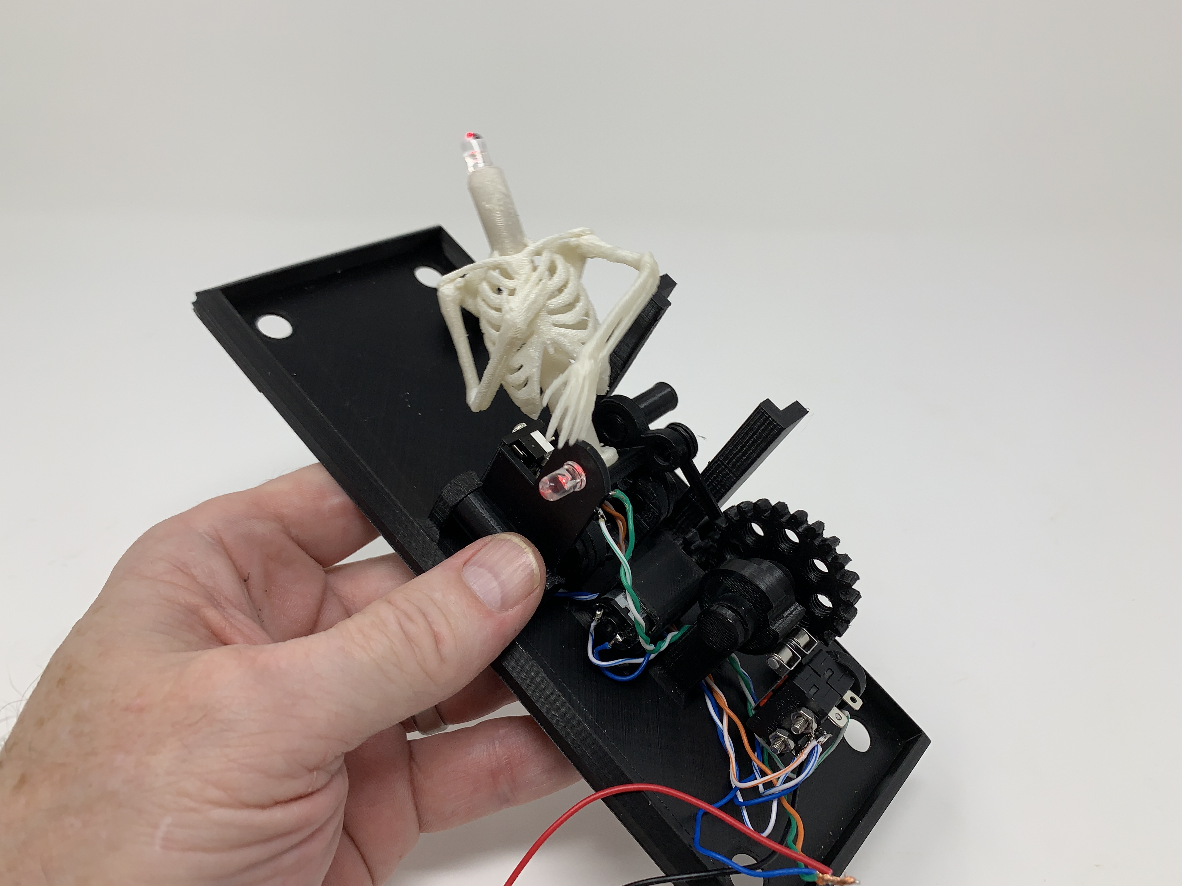
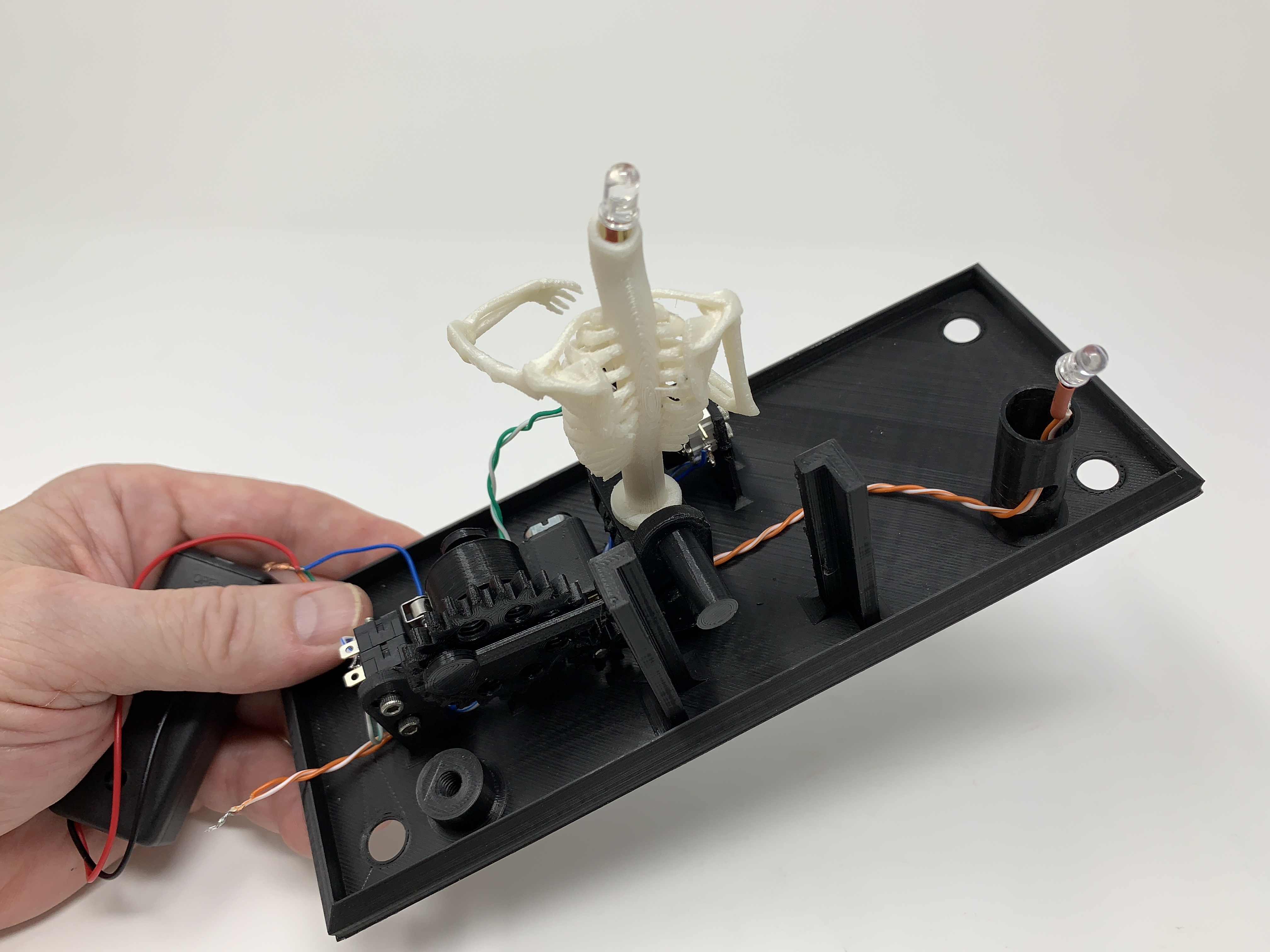
Add the Candles and Skeleton Head.
Note the tea light LEDs I salvaged run directly on 3VDC so no current limiting resistor are required.
To add the candles and skeleton head, I performed the following steps:
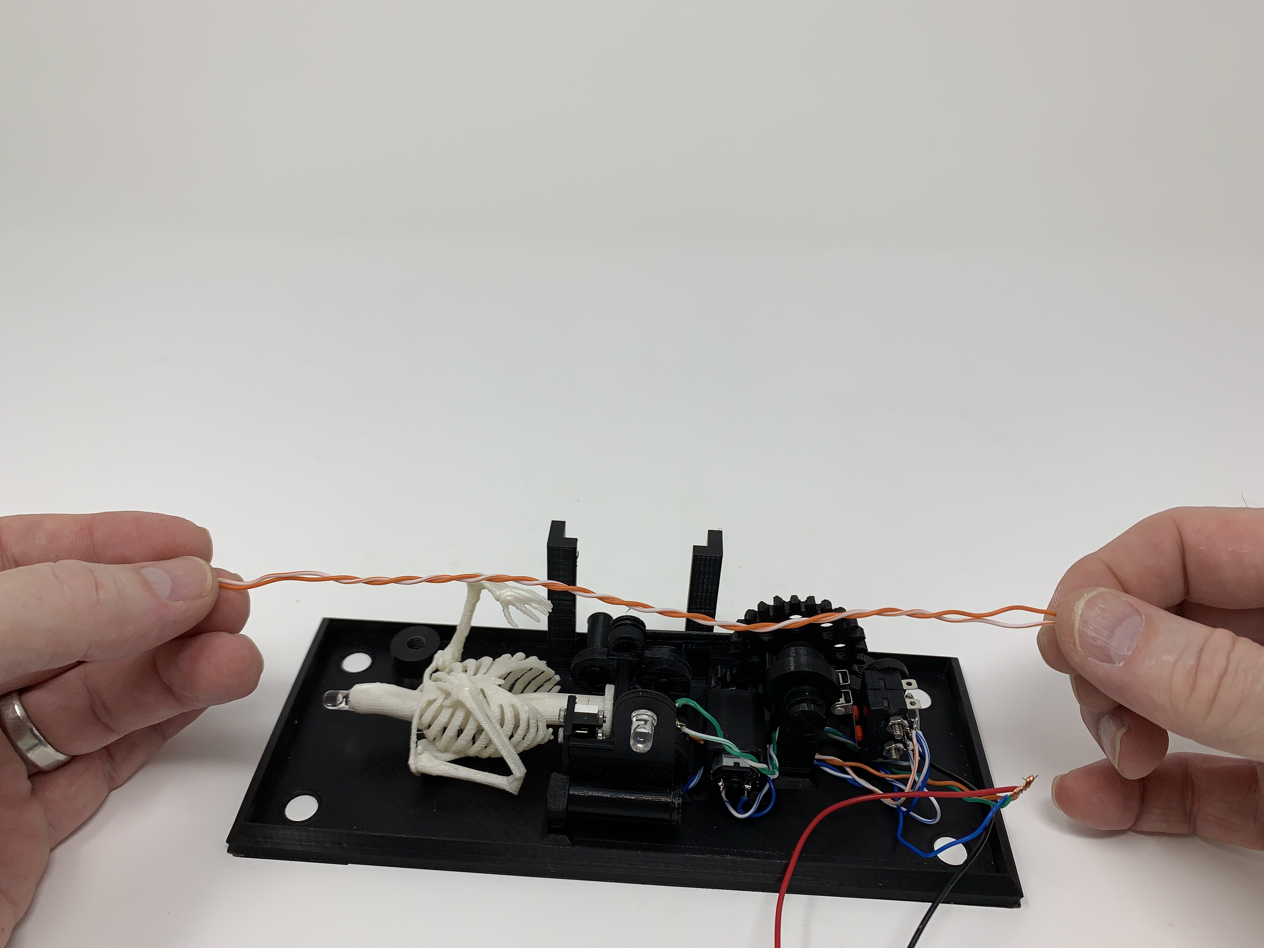
• Cut a 150mm length of orange and white/orange twisted pair wire.
• Soldered the orange wire to the salvaged tea light LED anode lead insulating it with heat shrink tubing.
• Soldered the white/orange wire to the salvaged tea lightLED cathode lead.
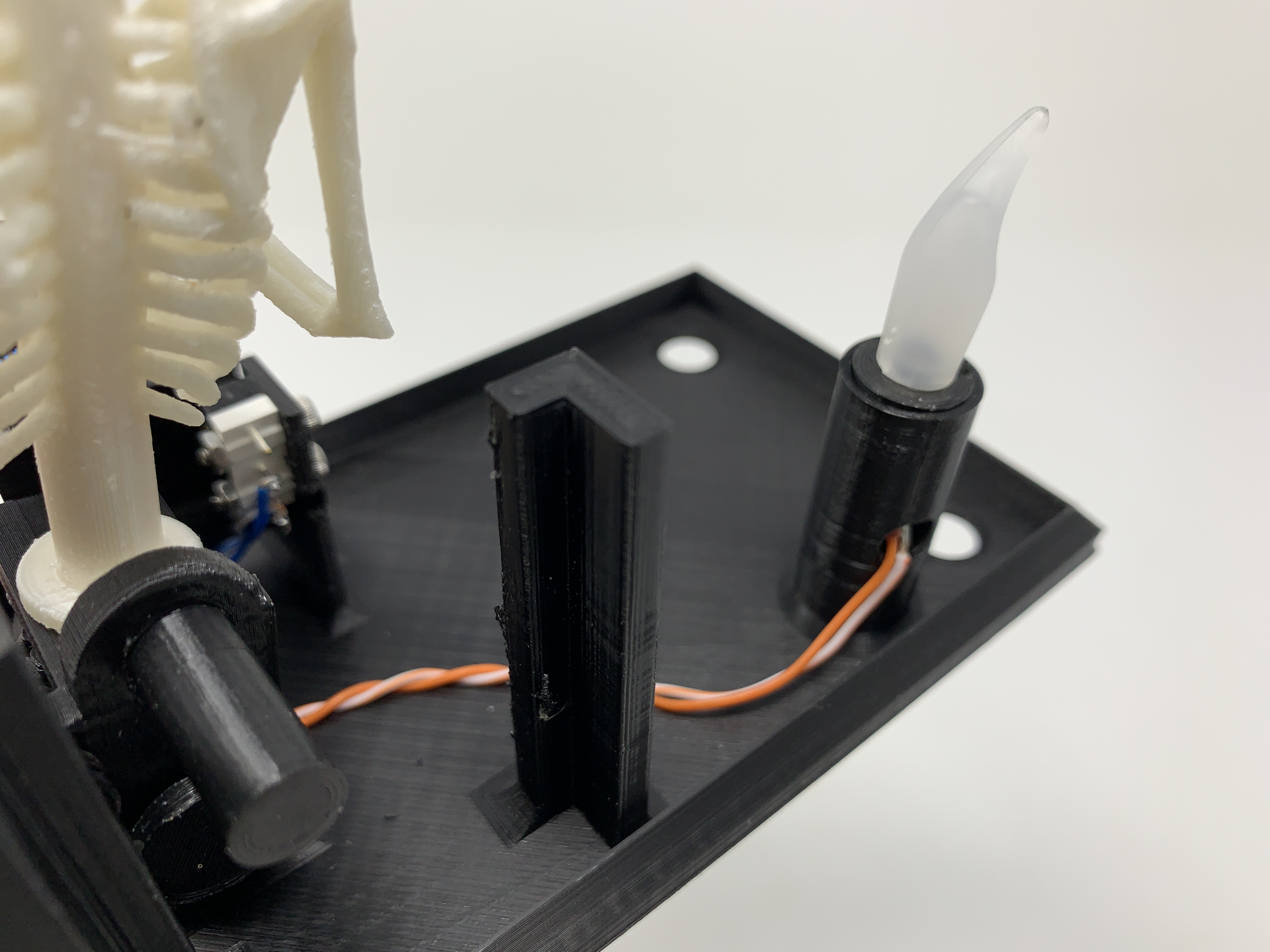
• Threaded one "Candle Holder.stl" into the right rear candle position of the base assembly.
• Threaded the wires through the candle holder, between the mount towers, under the motor mount, between the camshaft towers and out the left.
• Pressed the salvaged tea lamp flame into one "Adapter, Candle.stl".
• Pressed the salvaged tea lamp flame led into the tea lamp flame.
• Pressed the assembly into the candle holder.
• Soldered the white/orange wire to terminal 3 of the motor roller switch.
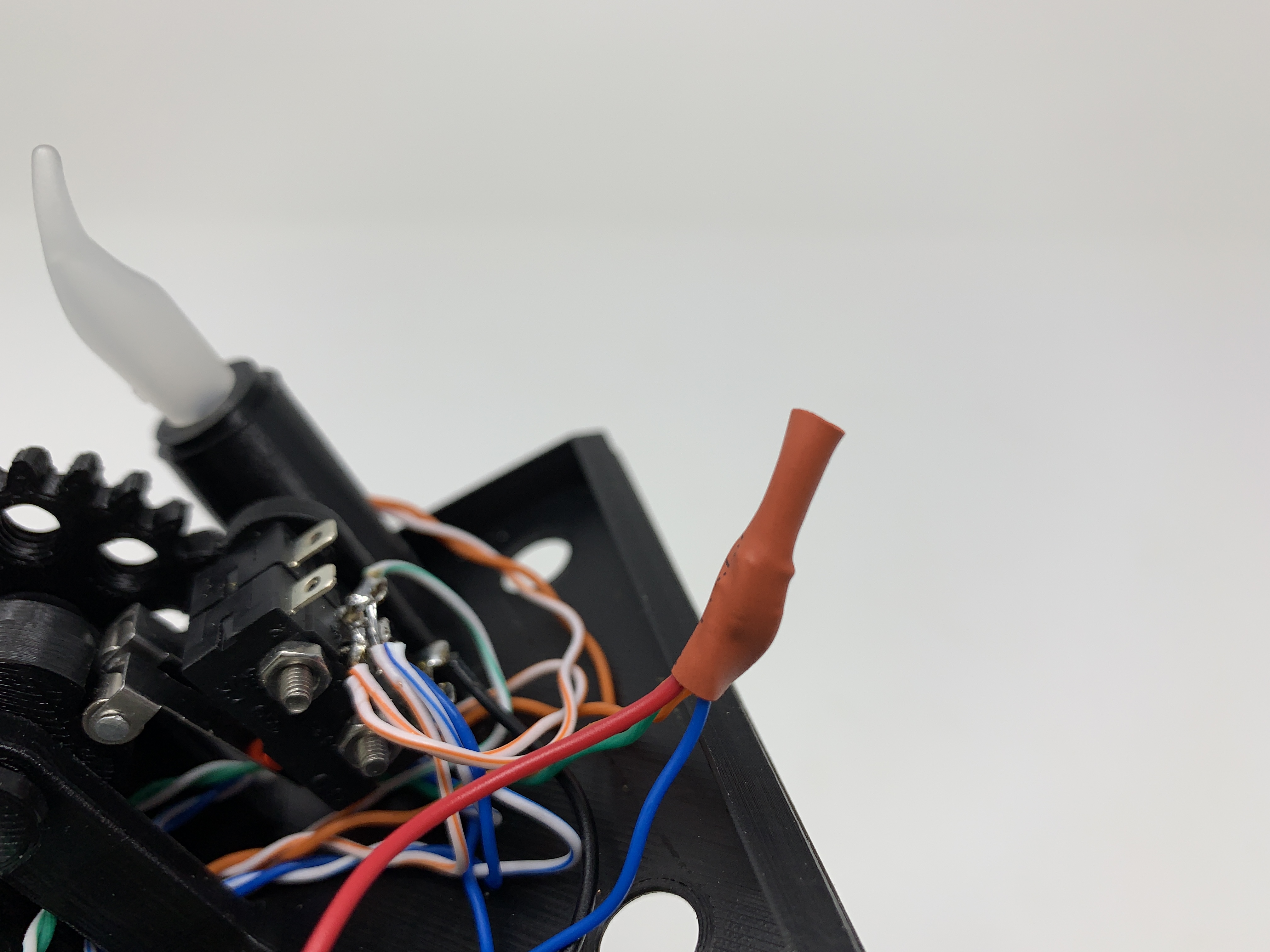
• Twisted the orange wire to the previously twisted battery holder red wire, soldered the bundle together, then insulated with heat shrink tubing.
• Repeated this process with the left rear candle using a 75mm length of wire.
• Turned the battery holder on/off switch to on.
• Pressed the pushbutton lever assembly and made sure the candles illuminated.
• Turned the battery holder on/off switch to off.
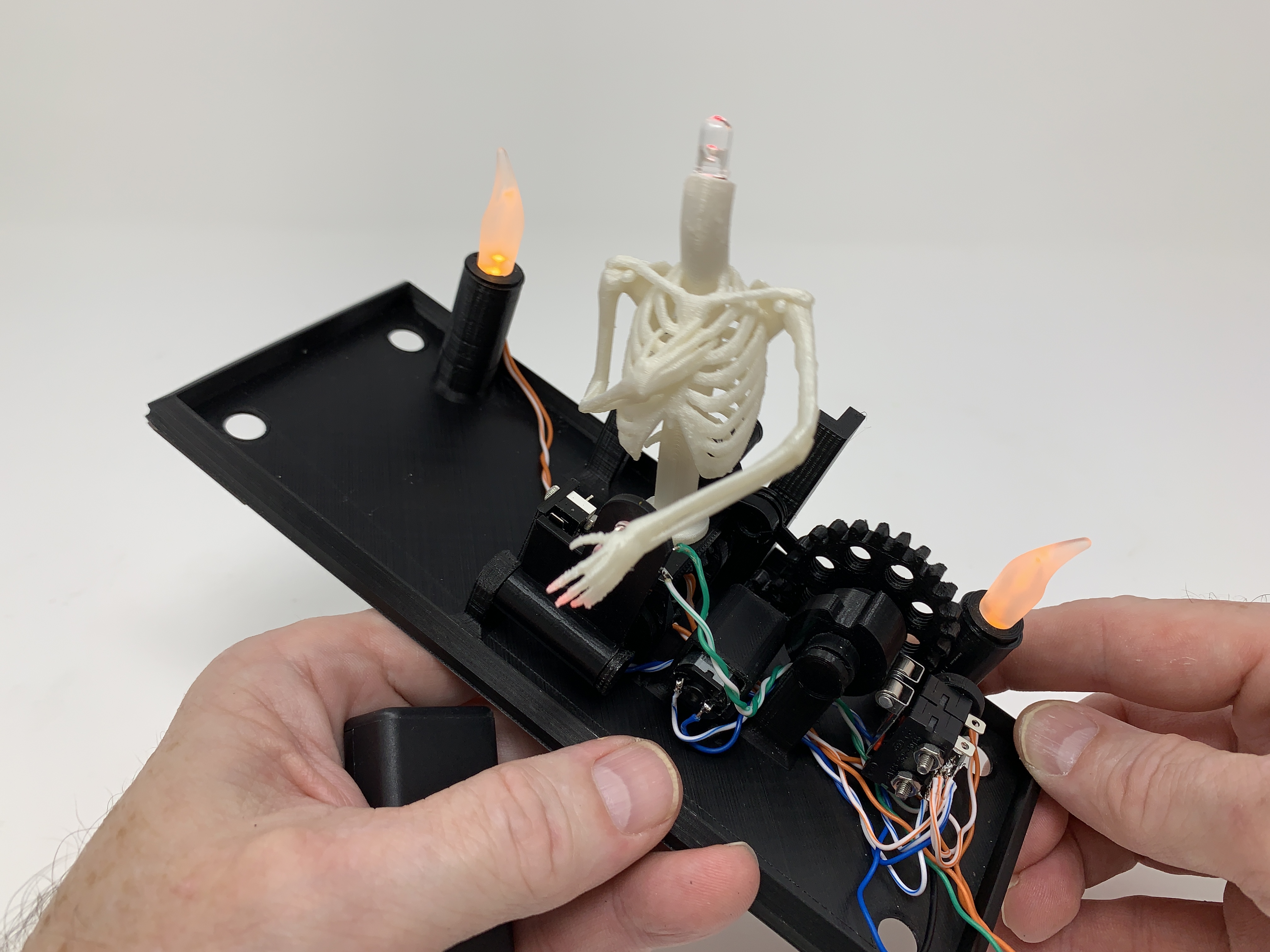
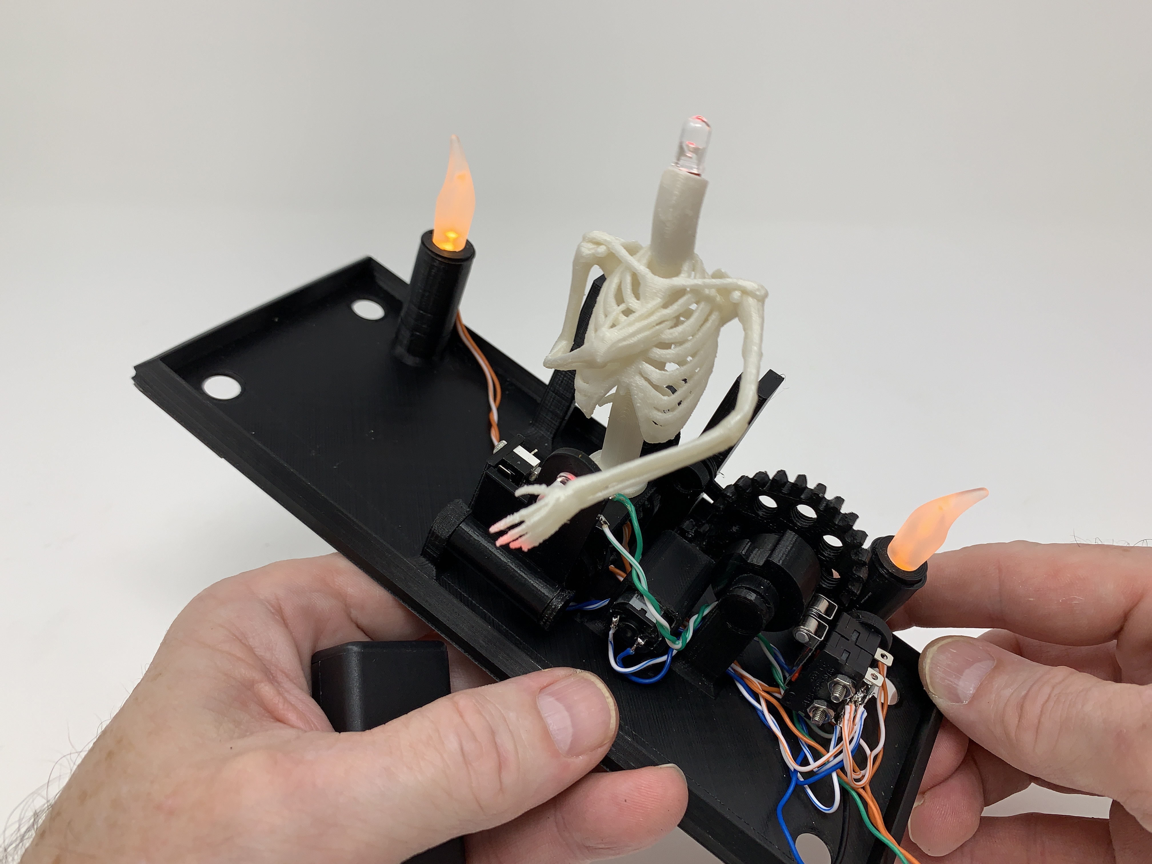
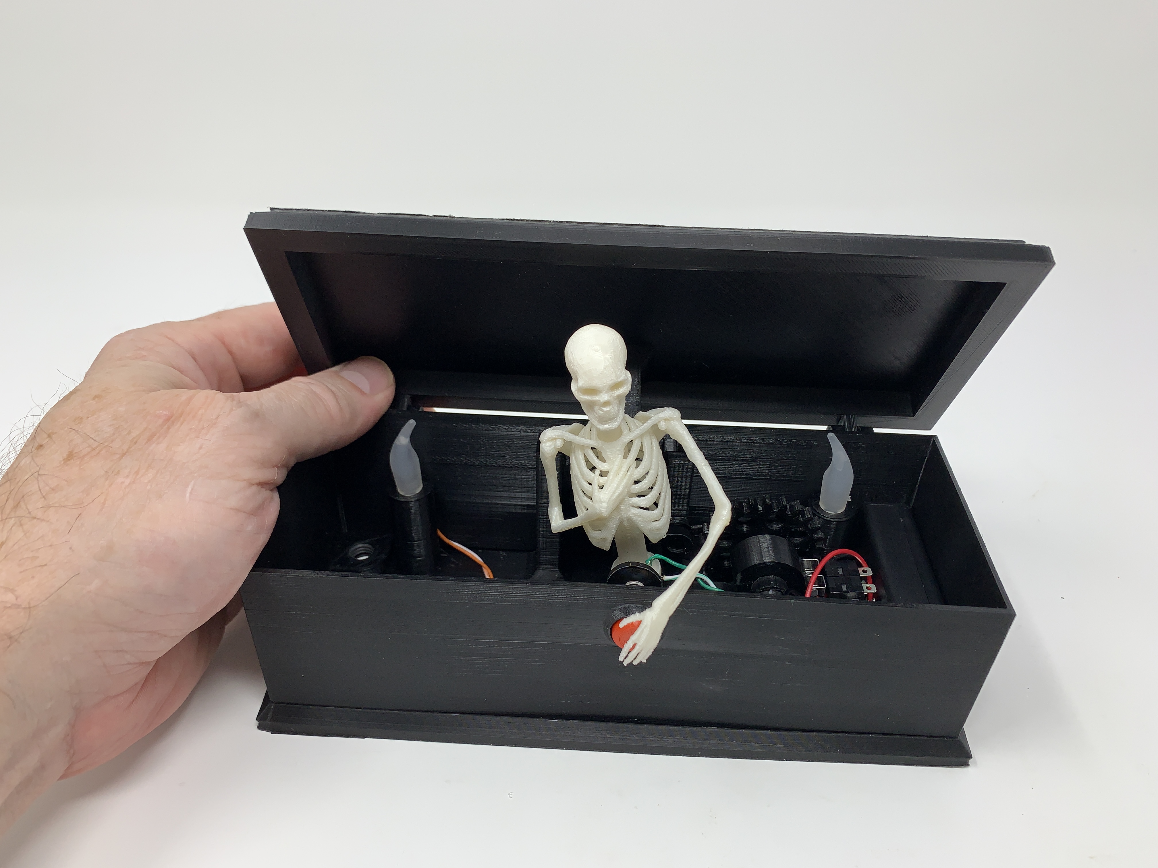
Final Assembly.
For final assembly, I performed the following steps:
• Positioned "Yoke.stl" over "Pin, Mount, Skeleton.stl" with the lid pin slot towards the front.
• Positioned the battery holder inside "Sides.stl".
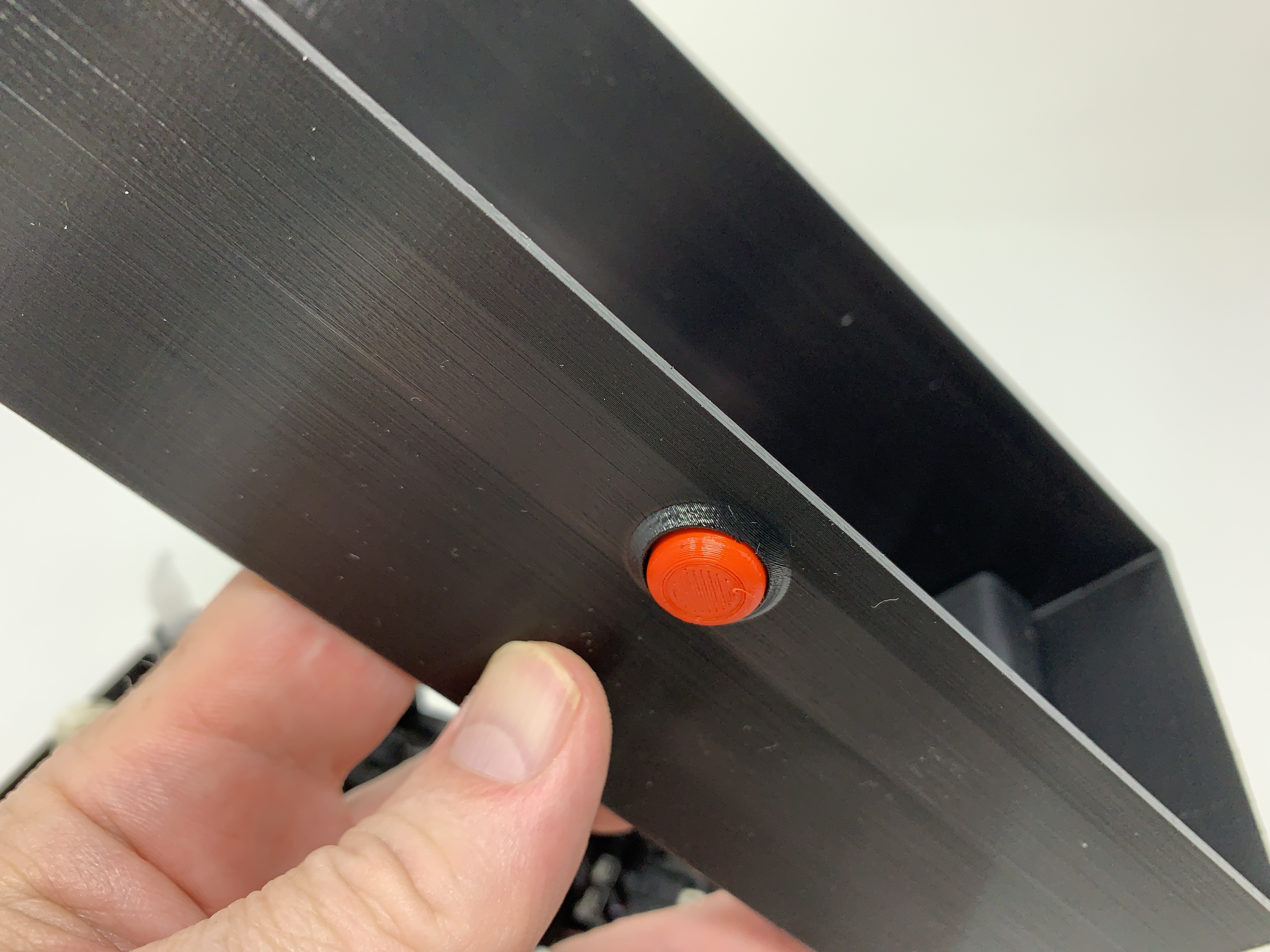
• Positioned "Button.stl" in "Sides.stl".
• Made sure the battery holder on/off switch was off.
• Pressed the pushbutton lever inward.
• Carefully positioned the sides assembly over the base assembly, sliding it downward until fully seated with the push button LED centered in the pushbutton.
• Turned the battery holder on/off switch to on.
• Pressed the pushbutton and made sure the mechanism cycled without binding.
• Pressed the pushbutton, waited until the skeleton was vertical, then immediately turned the battery holder on/off switch to off.
• Threaded "Pin, Lid.stl" into the lid arm from the right side of the lid (on the skeleton side of the lid arm).
• Carefully positioned the lid pin in the base yoke pin slot, rotated the lid, then positioned the lid hinge pins in the base hinge pin slots.
• Secured the left and right lid hinge pins in place using the two "Axle, Lid.stl".
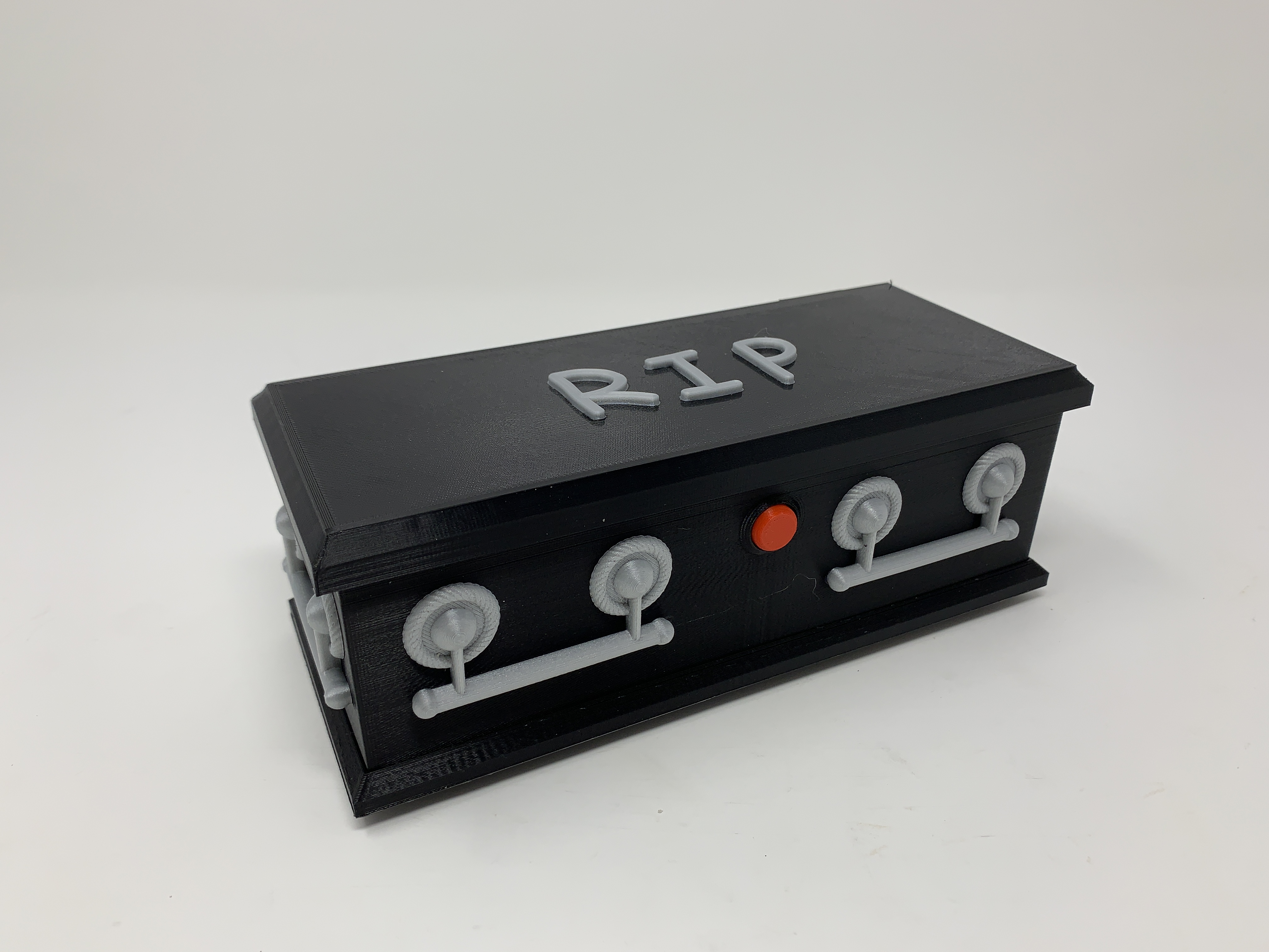
Once assembled and tested, I attached the four "Handle.stl" and "Lid, RIP.stl" to the coffin using small dots of thick cyanoacrylate glue.
And finally, when the batteries expire, how do I open the lid to change them since the pin slot mechanism holds the lid closed? There is a 10mm access hole on rear of "Sides.stl" aligned with the gear motor shaft and motor gear. First, I use a flat punch or equivalent to slide the motor and motor gear toward the front of the model just enough to disengage the motor gear from the camshaft gear. Next, using a dental pick, jewelers screwdriver or equivalent, I rotate the camshaft gear tooth by tooth until the lid is open. Once open, I remove the battery holder, replace the batteries, reinstall the battery holder, and finally reposition the motor and motor gear.
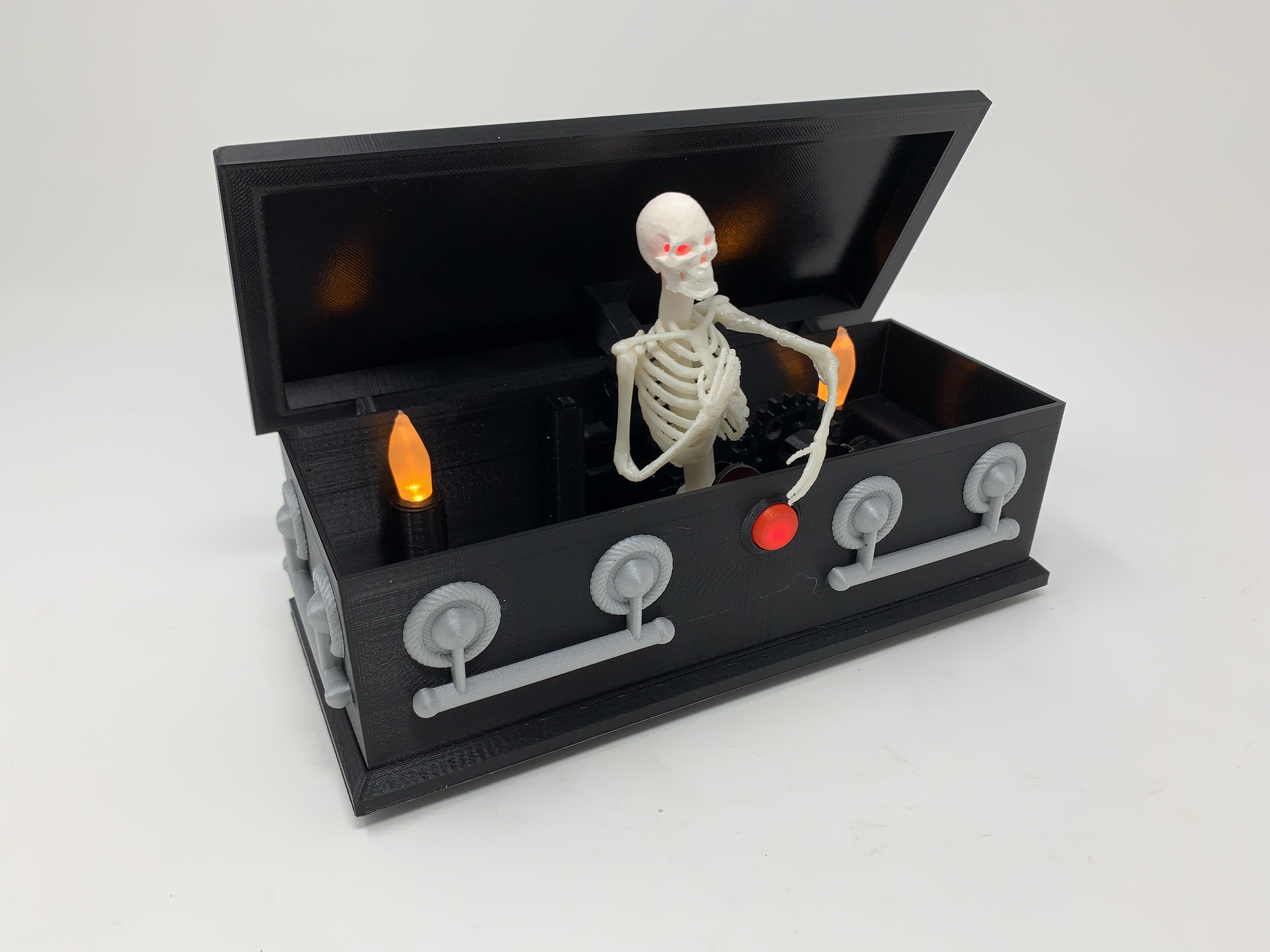
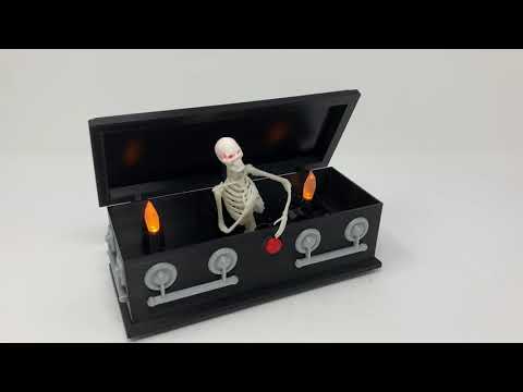
And that is how I 3D printed and assembled "RIP, Skeleton".
I hope you enjoy it!
:format(webp)/https://fbi.cults3d.com/uploaders/13550170/illustration-file/a76142b5-38d3-42e6-bac3-eb66ea3fe592/Image0000a.JPG)