Skip to content

Clerget 9B rotary aero engine

Advertising
?
Creation quality: 5.0/5 (2 votes)
Evaluation of members on the printability, utility, level of detail, etc.

  • 5.1k views
  • 7 likes
  • 131 downloads

License
3D design format
STL Folder details Close
  • Crankcase_front_-_Medium.stl
  • Crankcase_rear_-_Medium.stl
  • Engine_Stand_-_9.stl
  • Engine_Stand_-_9hole.stl
  • Engine_Stand_-_B.stl
  • Engine_Stand_-_Base.stl
  • Engine_Stand_-_Bhole1.stl
  • Engine_Stand_-_Bhole2.stl
  • Engine_Stand_-_C.stl
  • Engine_Stand_-_Engine_mount.stl
  • Engine_Stand_-_Rear_mount.stl
  • Engine_Stand_-_e1.stl
  • Engine_Stand_-_e1hole.stl
  • Engine_Stand_-_e2.stl
  • Engine_Stand_-_e2hole.stl
  • Engine_Stand_-_g.stl
  • Engine_Stand_-_ghole1.stl
  • Engine_Stand_-_ghole2.stl
  • Engine_Stand_-_l.stl
  • Engine_Stand_-_r.stl
  • Engine_Stand_-_t.stl
  • Exhaust_pushrod_1.stl
  • Exhaust_pushrod_2.stl
  • Exhaust_pushrod_3.stl
  • Front_flange.stl
  • Induction_tube.stl
  • Inlet_Pushrod_1.stl
  • Inlet_Pushrod_2.stl
  • Inlet_Pushrod_3.stl
  • Propeller_1.stl
  • Propeller_2.stl
  • Propeller_3.stl
  • Propeller_4.stl
  • Propeller_5.stl
  • Propeller_6.stl
  • Propeller_7.stl
  • Rear_Flange.stl
  • Spark_plugs.stl

Learn more about the formats

Publication date 2020-02-11 at 12:36
?
Published to Thingiverse on: 2019-09-30 at 11:24
Design number 107610

3D printer file info

3D model description

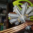
Scale model of a Clerget 9B rotary aircraft engine, as fitted to the Sopwith Camel during WW1.

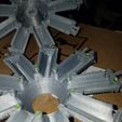
This model is based on https://grabcad.com/library/clerget-9b-radial-engine-1, which is a wonderfully detailed 1/4 scale model including every nut, bolt, and ball bearing. I've adapted this model for 3D printing. There is more detail in the model than can be printed with a 0.4mm nozzle. In particular, the cylinder fins didn't print well for me.

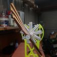
The engine mount is my interpretation of what a Sopwith Camel engine mount appears to be, with a frame below to support it.

The model in my photos is slightly different from the design which I'm uploading; the uploaded design is improvements based on what I found when I built my model. One detail is that the wiring for the electric motor can be brought out through the brush-holders on the rear of the central support, where the ignition wires of the real motor attach. There's also a "rear support" you can add to the rear of the mount.

The engine's scale is 0.117 (between 1/8 and 1/9)... this arbitrary number is based on a Sopwith Camel with a 1m wingspan. Scaling up or down my STLs in a slicer would only work to a limited amount. Scaling up would result in the motor shaft being too short to go right through the prop. Scaling down would require drilling out the shaft hole back to 3mm.

A few of the parts (propellor, pushrods, engine mount, base) are designed for dual extruder printing. Merging all the subparts should allow printing on a single extruder.

I've glued all the parts together with 5-minute epoxy. Probably cyanoacrylate would be just as good, but epoxy does have a space-filling capability that CA doesn't.

One slight imperfection that a purist may notice is that all the valves and pushrods are in the same position. I'll leave it to the purist to remix the model so all the valves are in the correct positions.

Extrusion of the blue stopped midway through the print of the base; I have other things to do, so I can't be bothered redoing that.

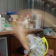
Inside the model is an N20 gearmotor with a 55mm M3 shaft e.g. https://www.aliexpress.com/item/32956961754.html -- I chose the 400RPM version. Running off a 9V battery, I guess it's spinning about 300RPM, which is plenty. The motor slides sideways into the mount (see the yellow test print of the mount. NB: make sure it is the right way round!) which is then screwed to the engine mount with 2.5mm self-tapping screws.

Glue an M3 nut into the rear of the front crankshaft half, and into the recess in the propellor front flange. Glue short pieces of filament into the alignment holes in one of the crankshaft halves, and trim back to about 1mm proud of the surface. Glue the halves together with slow-setting epoxy) and glue in the spark plugs with 5-minute epoxy. These are designed to help align the cylinder halves. Glue on induction tubes, then inlet pushrods, then exhaust pushrods. Glue flanges to propellor... NB: rear side of propellor is straight, front side is curved. Glue engine mount frame into base. Spin engine onto shaft until the motor is invisible, then hold the engine and tighten the propellor against it.

Advertising


Issue with this design? Report a problem.

Would you like to support Cults?

You like Cults and you want to help us continue the adventure independently? Please note that we are a small team of 3 people, therefore it is very simple to support us to maintain the activity and create future developments. Here are 4 solutions accessible to all:

  • ADVERTISING: Disable your banner blocker (AdBlock, …) and click on our banner ads.

  • AFFILIATION: Make your purchases online by clicking on our affiliate links here Amazon.

  • DONATE: If you want, you can make a donation via Ko-Fi 💜.

  • WORD OF MOUTH: Invite your friends to come, discover the platform and the magnificent 3D files shared by the community!


Sharing and downloading on Cults3D guarantees that designs remain in makers community hands! And not in the hands of the 3D printing or software giants who own the competing platforms and exploit the designs for their own commercial interests.

Cults3D is an independent, self-financed site that is not accountable to any investor or brand. Almost all of the site's revenues are paid back to the platform's makers. The content published on the site serves only the interests of its authors and not those of 3D printer brands who also wish to control the 3D modeling market.

100% secure payment by credit card, PayPal, Apple Pay, Google Pay, etc.
View all payment options.