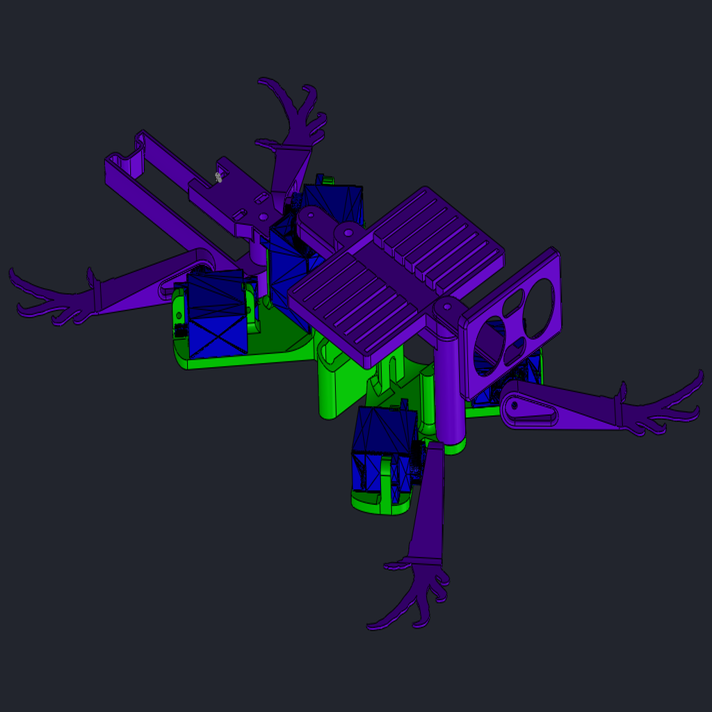
This was my final project for a postgraduate course in real-time operating systems (RTOS) applied on embebed systems. The objective was to make a project where we could apply he concepts of RTOS. I'll share here the printable parts I've used, as a frame for learning or trying a diferent method of locomotion in robots. There are many quadruped robots designs on Thingiverse, my design uses 5 servos for locomotion instead of 8 or more. On the other hand, the movility of this robot is hightly restricted when compared with others. The robot was powered with an 18650 battery and a simple charger-protection board, and controled by an Edu-CIAA board. It was originally designed for the smaller PicoCIAA, but never implemented. You could use other boards, like Arduino, and supply source if you want.
I have to thank Edmar Prado, who help me to restore this post, after being erased, I think, by accident by my fault.
The move of this robot was inspired by that of a lizard. Each servo controls a leg, and a fifth one the torso. In every step, two diagonal legs (for example the right front leg with the left rear leg) start raised and the other two down, the torso flexes to one side. Next, the flex torso to the other side and the legs that are down gets up and the other two get down. For turning, it is needed just to add some angle in the movement of the torso in some part of the march.
You must already know how to upload a program to the platform you would use. It is also preferable, but it can be learned in this lesson, to have previous experiences in programming PWM devices.
I propose some activities to do programming this robot:
First goal: Making it move
The first and basic activity could be to program and model their movement, to find the correct position sequence for each leg for a forward run.
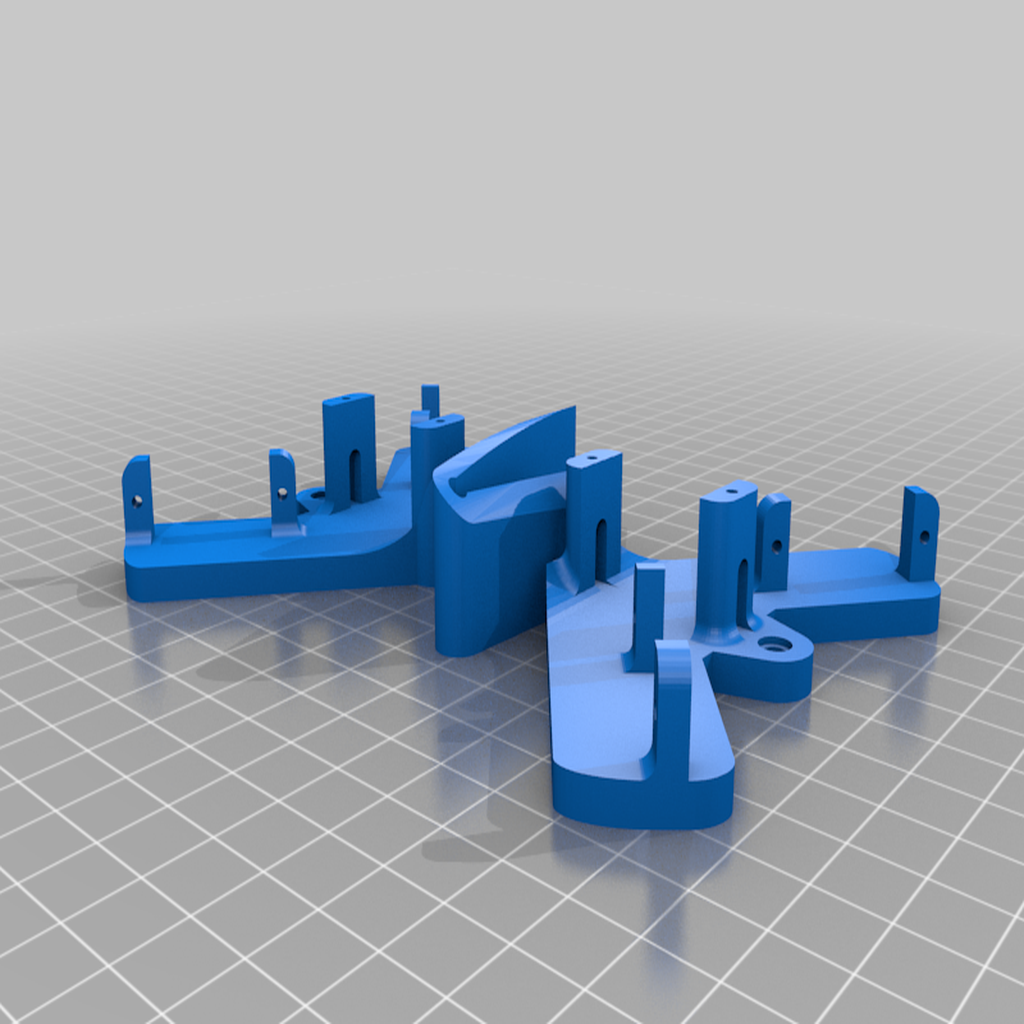
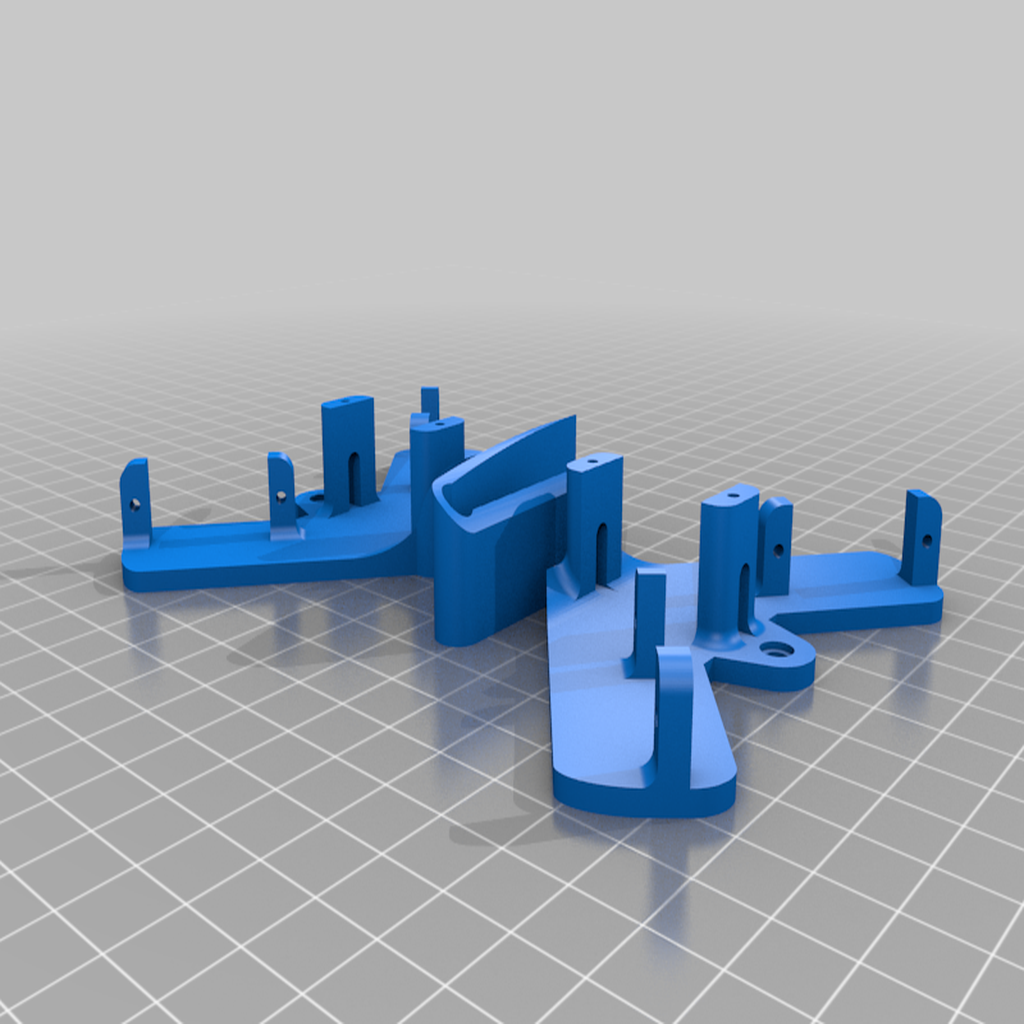
First step: assembly. The order and placement of the pieces are sufficiently explicit in the images in this post. All cards except the USB charger can be placed in the "boards.stl" part.
Second step: programming. Make the servo drivers or look for one ready. Remember that servos work with PWM signals, you can create a function that translates the desired angle to the duty cycle.
Third step: Find the sequence of the movement. Since the robot can move each member of its body, it needs to coordinate them. The activity resolves when you can move it by following a synchronous sequence of steps. You can change the speed of the robot by changing the time it takes to follow the sequence.
Step Four: Program more moves. If you're going to command the robot, you probably want to do more than just move on. You may need to change gears to turn left or right. You can also add the ability to get up and down.
Second goal: Command the robot
This activity could be done independently to the others, you could do it before the first one. You will need to communicate with your robot, to say it to go forward or back, to turn left or right, to stand up or rest. You will need to make or look for a driver for the communication you want to use with the robot. I used a HC-05 bluetooth module for this. It has a simple UART channel with the board. You can use this app to send letters to the module from your phone (there must be an iOS app for that too). Each letter the module receives and send to the UART channel to the board, there must be a function to recognise it and control the movement o the robot.
Another communication method may be by RF modules. The advantage of this method is that they have a lower power consumption, and they are faster than bluetooth, though the rate of the communication signal doesn't need to be fast, since the rate of the servos is low (20Hz) they cannot change its angle faster than that. The disadvantage of his method is that you will need another embedded system to emit the RF signal, you could not use a phone or that.
Third goal: Optimice the movements
A final and optional objective could be make the best sequence of movement for a faster walk or the most economic (in battery power). I see two ways to do that: one could be proposing different strategies for the step sequence; the second way could be start with a sequence and program the algoritm for making the robot learning. The learning mechanism would be possible only with a feedback method, like the ultrasonic or infrared sensor. For the power consumption a Hall effect current sensor could be fine.
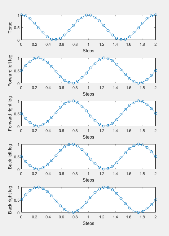
Sinusoidal
The only sequence I tested is a sinusoidal distribution. Thus, every servant has a sinusoidal sequence, with a sine offset by + or - 90 degrees to the legs. This march is quiet, but it is expensive to consume because the servos are in constant motion.
Sinusoidal sequence. The x axis is the number or fraction of the robot's walking step. The y axis is the percentage of the maximum-minimum angular range that you set for servos. Graphs made with MATLAB R2016a.
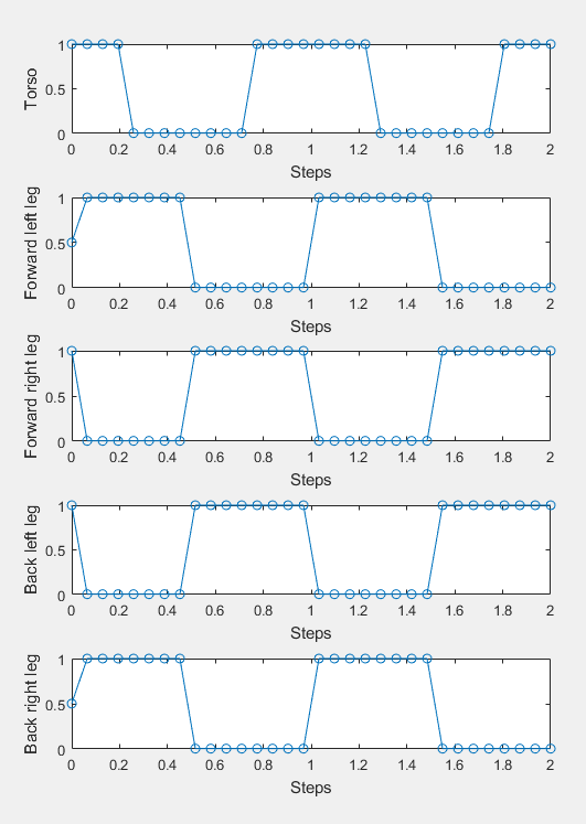
Yes or No
This coding is simple, the leg is up or down, the torso is rotated left or right. By this method, two legs are up, then the torso turns, then the legs change. The advantage is that the servos are not constantly moving, which ensures maximum consumption when the servos are moving at the same time. Leg speed is limited by servo capabilities. The main disadvantage of this method is that everyone except the torso servant is moving at the same time, which means that the energy required for this moment can cause the voltage to drop to a dangerous level, which can cause the plate to restart, depending on the allowable charger board current.
Yes or no sequence. The x axis is the number or fraction of the robot's walking step. The y axis is the percentage of the maximum-minimum angular range that you set for servos. Graphs made with MATLAB R2016a.
Materials needed
1 TPU "body_flex.stl" print or 1 "body_rigid.stl" print on any rigid filament.
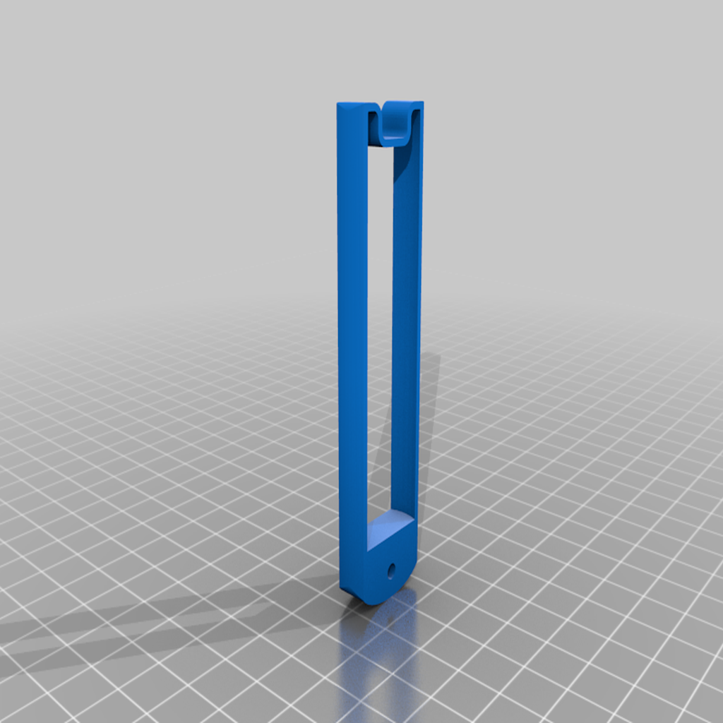
1 print of "backbone.stl" on any rigid filament.
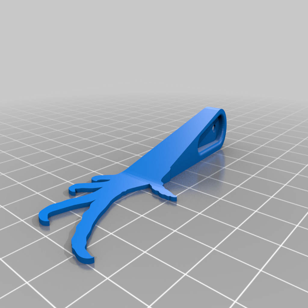
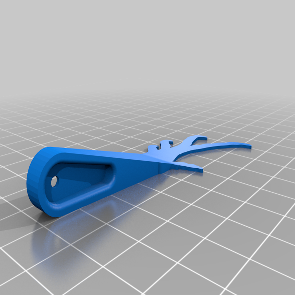
2 prints of "foot.stl" on any rigid filament.
2 impressions of "foot_mirror.stl" on any rigid filament.
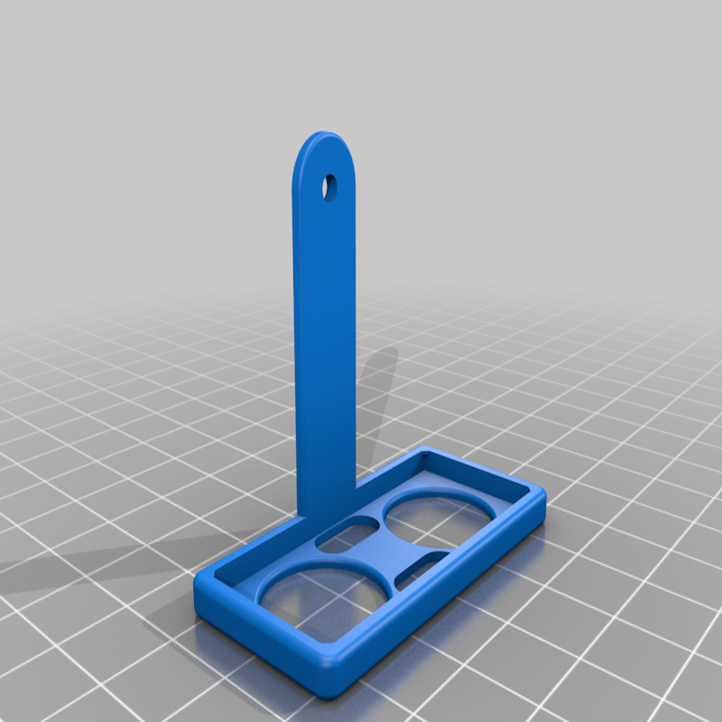
1 print of "battery.stl" on any rigid filament. If you want to provide power externally (without battery, but wired), this part is not required.
1 print of "usbcharger.stl" on any rigid filament. If you use another charging card or want to provide power externally (no battery, but wired), this part is not required.
1 print of "boards.stl" or "big_boards.stl" on any rigid filament. The large (untested) version is for cards like Arduino UNO. You do not need both.
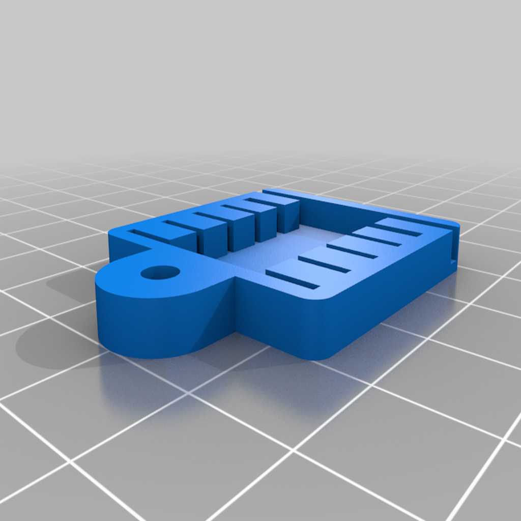
1 print of "us_sensor.stl" on any rigid filament. Not tested. Optional for a feedback method.
5 servants Sg90.
Anything that can control 5 PWM signals, such as an Arduino or any qualified embedded system.
One usb charger for 3.7V batteries. The part "usbcharger.stl" is designed for this charger whose output voltage is directly the battery voltage (from 3.5V to 4.2V). You'll need to go one step further to use with 5V cards (like most Arduinos), or another charger card with an onboard outlet. If you use another charging card or want to provide power externally (no battery, but wired), this component is not required.
1 18650 battery. If you use another battery format or do not use the battery, the "battery.stl" part is not required.
M3 12mm screws. Nuts are not required.
Several 2.54mm connector wires.
A bluethooth card, or an RF card if you want to remotely control the robot (I used the HC05 card with this app).
An ultrasonic proximity sensor. Optional for a feedback method.
Feedback me!
If you try one of the proposed strategies or develop a new one, you would be happy to see it. The project ended a little unfinished, so I will be open to any suggestions.
:format(webp)/https://fbi.cults3d.com/uploaders/15008782/illustration-file/c024f4fb-0f67-4cef-8e75-db6576820781/robot_setup.jpg)


/https://preview3d-images.cults3d.com/ii5126he8ymo0r4p9bocbvcruz2u)
/https://preview3d-images.cults3d.com/xc2z7so095yk0e5u8b33seaswcgb)
/https://preview3d-images.cults3d.com/6k4r6d26e7zd21rtqa4mbfc3vweh)
/https://preview3d-images.cults3d.com/d8v2ggd1abp0aiqydyap3i9hx6rx)
/https://preview3d-images.cults3d.com/ahi3r53xpyfq1udiq8m7zi40x83v)
/https://preview3d-images.cults3d.com/f32zr9mfrwo3h4aqniig7i8bb1yi)
/https://preview3d-images.cults3d.com/euhdfccbt6au3f4kyfberzw5wmw9)
/https://preview3d-images.cults3d.com/d28h82twdhpnv7g2v3kq9lk2lvxo)
/https://preview3d-images.cults3d.com/iepfmkdzcbc79zckg63kcwnpd37s)
/https://preview3d-images.cults3d.com/vtxfvb5mt9hq1il5va3gz7j6v2sr)


