-Print Settings
Supports: Yes
Resolution: 0.2mm
Infill: 20%
Filament: Hatchbox PLA
Notes:
I used supports for the top halves because of the recesses for the switch clips and stabilizers. For the bottom halves, i do because of the overhanging screw holes.
You can try without, but the supports are small in this case
Post-Printing - the photos of these steps are in the files
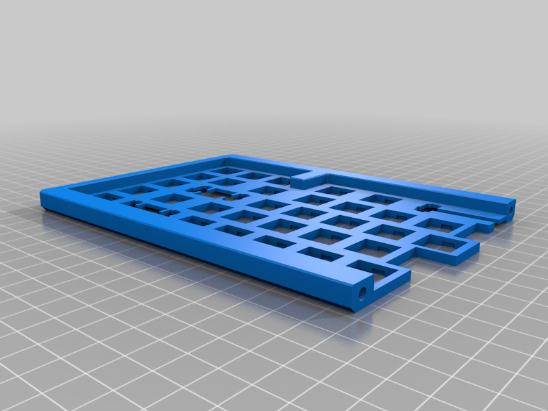
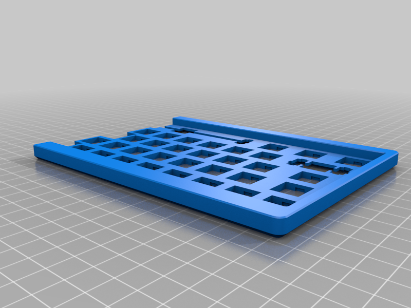
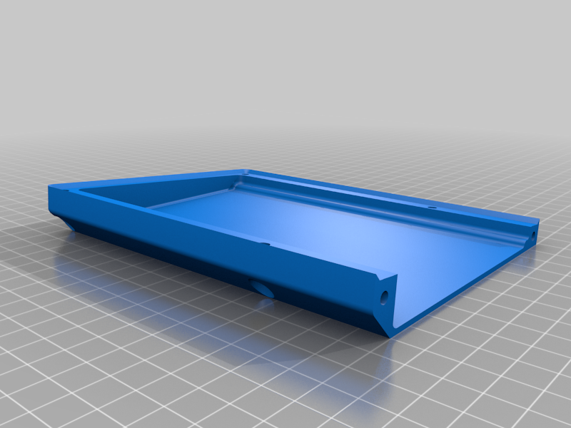
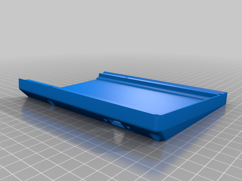
Print and assemble the individual parts
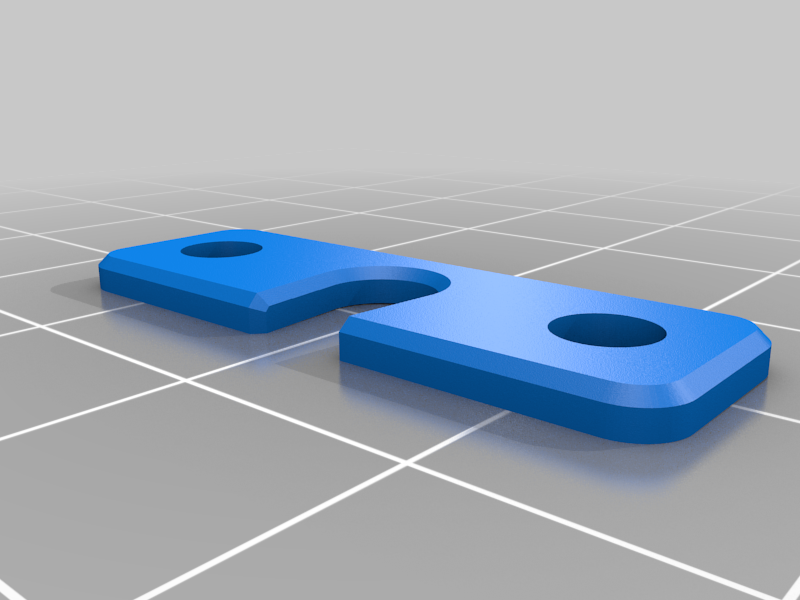
I designed the parts to be pinned with 3.5 mm rods - in this case bamboo skewers work nicely.
I use gel superglue to fix the two parts together
Assemble the top and bottom and Rough Sand
Once the glue has cured, assemble the top and bottom halves with M4 x 12 screws (i use hex socket insert machine screws)
Then use 220 - 320 grit paper or block to rough sand the planes. the object here is to reduce the layer lines and heavy marks to prepare to fill the imperfections.
You will see how good your layer alignment really is in this step
Disassemble and Fill all the surfaces with glazing putty
Disassemble the top and bottom then wash with mild soap and water.
I use bondo glazing putty for this part, its easy to spread with a single-edge razor blade and dries relatively quickly. It also is easily sandable.
I spread it in a heavy layer while pushing it into the recesses.
Its important to do this on the top and bottom halves while they are separate, you don't want to fill the gap between the top and bottom halves.
Once its dry, sand again with a 320 block to remove the excess material, and then 400-600 grit to smooth out the surfaces.
Repeat this process as necessary.
You can assemble the top and bottom halves to wet sand with 600-800 grit if you need to check fitment and alignment
lots of putty
most of it gone, this is what you want
repeat for little chips or places you missed
nearly done
Test Fit Switches and Stabilizers
Test fit a few switches and the stabilizers at this point.
Make sure the switches fit tightly and the clips lock in the recesses
Make sure the stabilizers are snug, but fit ally the way against the plate, and are not squished - they should move freely.
Use a hobby knife or small files to clean up any of the mounting holes
Paint!
I use rustoleum 2x since it bonds well to plastic and it comes in a large variety of colors. In this case i had some charcoal grey from theFilclone left over and i like the satin finish.
Lookup some guides for spray paint, and follow the manufacturer's instructions for ventilation, etc.
you can see i dealt with a little crazing by not waiting long enough for a second coat - if that happens to you, let it thoroughly cure, then back to 220-320-then maybe 400 or 600 grit and paint again
Handwire!
I have used the brownfox method on deskauthority for many keyboards, works well
switches and stabs fitted
Here is an explanation of the stabilizer cutouts - the red area is utilized by the cherry style, while the blue area is utilized by costar
diode rows and monofiliment (or enamel coated magnet winding) wire columns
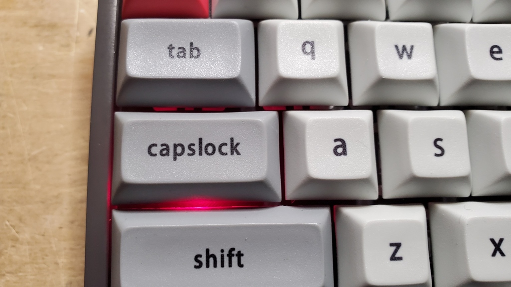
3mm LEDs hot glued (minimal - less is more) into position on the capslock and left bracket keys. (Fn+left Bracket is scroll lock)
caps fitted, except for LEDs for testing
LED through the key
hot glue!
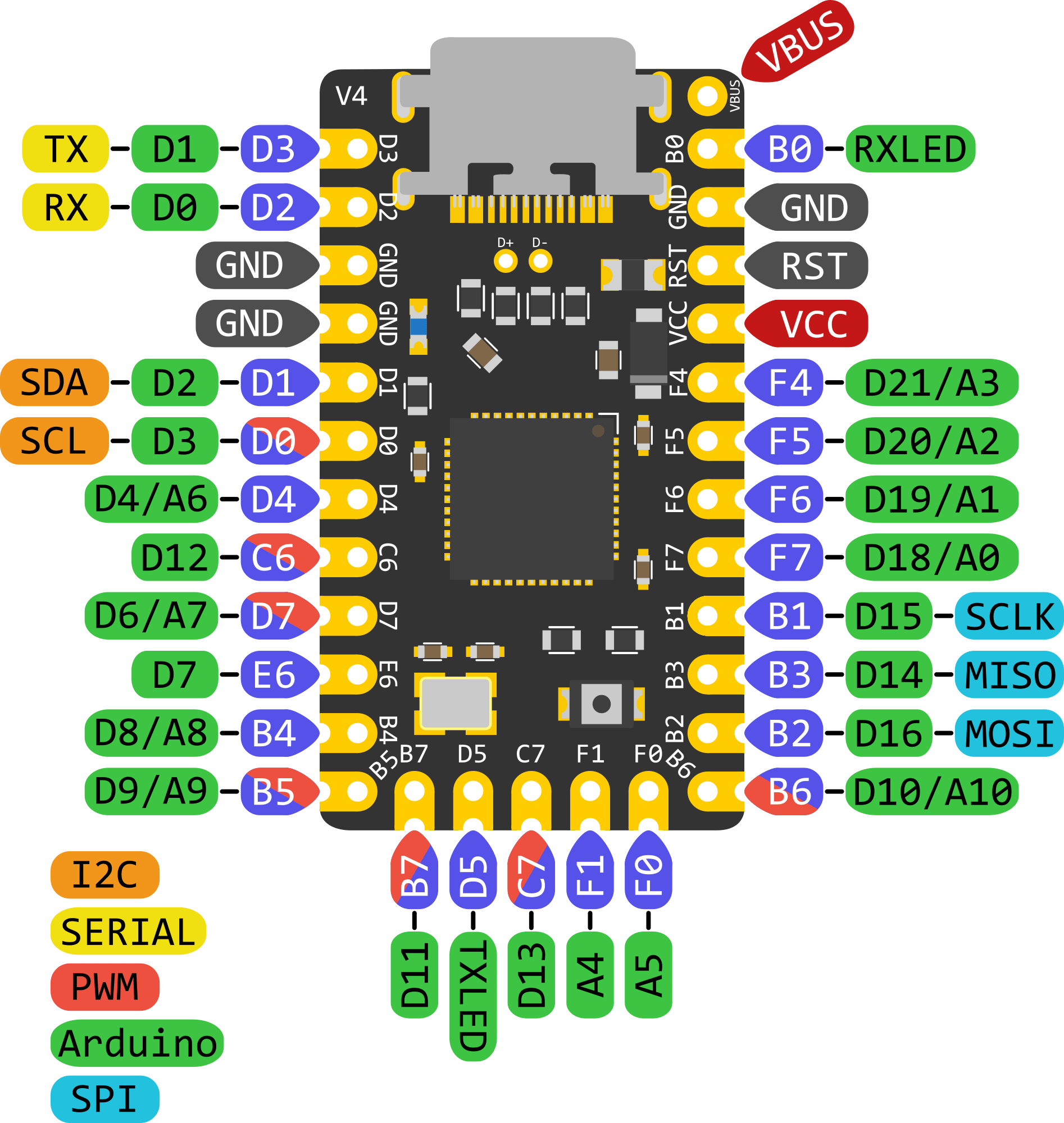
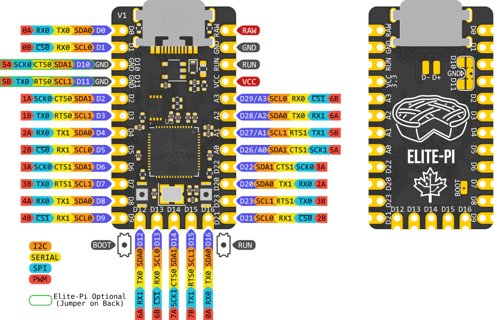
Preparing the teensy - slip off the standoffs from the pins
i use my square cutter to gently pry them up, working one side at a time back and forth
i then gently bend the pins 90 degrees to 'splay' them out - don't snap them off! and wire my pins with female jumpers (if i straight soldered here it may have fit better without the spacer). Note that I intentionally left the design so you could use whatever controller you want, and uploaded STEP files for modifications to the case to suit
LED Wiring
since its not always clear - for this firmware wire the negative side of the LEDs to the pins on the teensy, and a common wire from VCC (3.3v positive) to the positive side.
I used 3 volt 25mA 3mm low intensity LEDs so no resistors were needed - you may choose differently, and then need LEDs
Final Assembly
Try as i might, there was just not enough room for the teensy 2.0 in my case, YMMV - so i added the 3mm MID-SPACER parts to give it some more room. I might paint it later - maybe red?
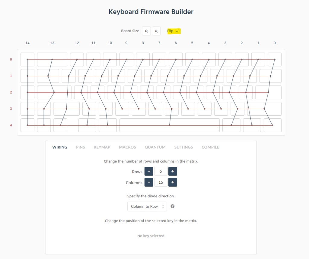
then flash the firmware on your controller.
I used https://kbfirmware.com/ - if you upload thealternate.json there, you can edit pins, wiring, keymap and recompile (its based on TMK/QMK). at some point i may develop a QMK proper firmware, but this one works
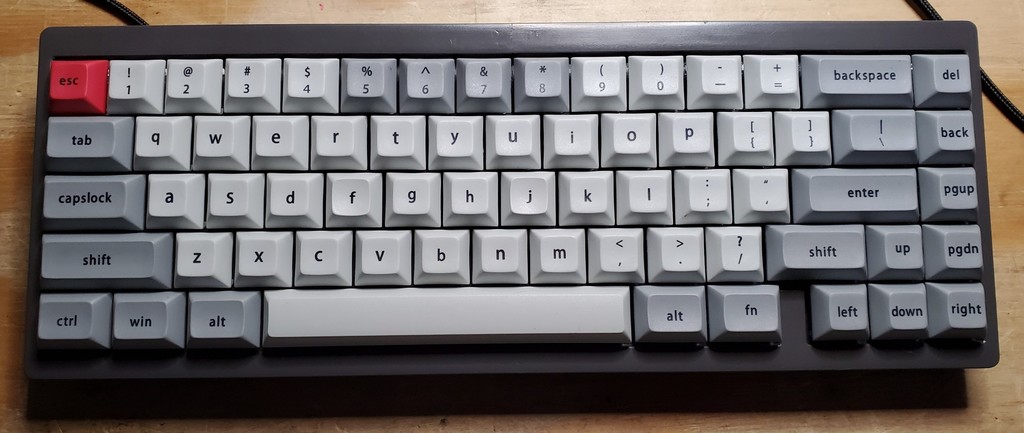
backlit capslock!
How I Designed This
Keyboard Stuff
You can mock up the layout of pretty much any keyboard layout you can imagine here - http://www.keyboard-layout-editor.com/
I use the swillkb plate builder to get SVGs of my switch and top layers, you can import them in your design program and loft or extrude to give them some mass, and then start building around them.
I generally start with the basic shape geometry of the keyboard, then make it a shell. From there i merge the switch and top layers (or just the top layer if i plan to use a metal plate). then you add your fastening mechanism (screw holes) and cutouts for the cable, etc.
you pretty much have a keyboard at that point, and you just need to verify measurements, add design elements, make sure joints are strong (fillets work great to strengthen two intersecting flat plates). Last step is to divide it up to fit on your print bed and cut-out pin recesses.
I print from there, and as i assemble, I tweak my model as needed to make it better for then next person who prints.
Its good to remember that plastic is melt-able and easy to cut or file/grind - so make it work as needed!
:format(webp)/https://fbi.cults3d.com/uploaders/16492722/illustration-file/2830c2b9-10a1-412c-8f34-b561114761cd/20200511_192638.jpg)

/https://preview3d-images.cults3d.com/g3d8zg3addryoe484nh8m9hxtckx)
/https://preview3d-images.cults3d.com/alqoda2cptffat4ic0eo8wl7re9l)
/https://preview3d-images.cults3d.com/i8antdhje5uypkihsiwv5sommxnq)
/https://preview3d-images.cults3d.com/xsz80bzi5yma3z4hgh4gprs05t2k)
/https://preview3d-images.cults3d.com/o0z8l1i73z4g0jre4dm3c898y0cj)
/https://preview3d-images.cults3d.com/r0hyyew6g4tk2nm85fxnm4txmdvg)
/https://preview3d-images.cults3d.com/6ub41hlxexx67vsfiv6ggr66bx7e)


:format(webp)/https://fbi.cults3d.com/uploaders/16492722/illustration-file/c5af44ae-c91f-4255-adc0-dc5813caa44e/20200411_151902.jpg)
:format(webp)/https://fbi.cults3d.com/uploaders/16492722/illustration-file/4b9eec8f-9ec2-4248-9052-44a0484bc913/20200408_191626.jpg)
:format(webp)/https://fbi.cults3d.com/uploaders/16492722/illustration-file/18e6ebb3-36cb-4e1c-a1e4-0d0d3879ab53/20200403_113641.jpg)
:format(webp)/https://fbi.cults3d.com/uploaders/16492722/illustration-file/b1964893-0d3e-4d1b-ac7d-3db9fea93c23/20200329_114304.jpg)