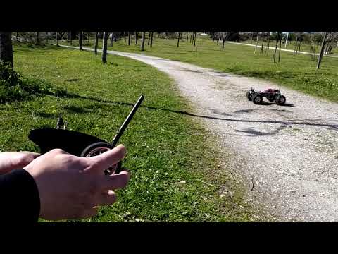
https://youtu.be/m5H8ZL3efo0
https://youtu.be/VcryeB61UpQ
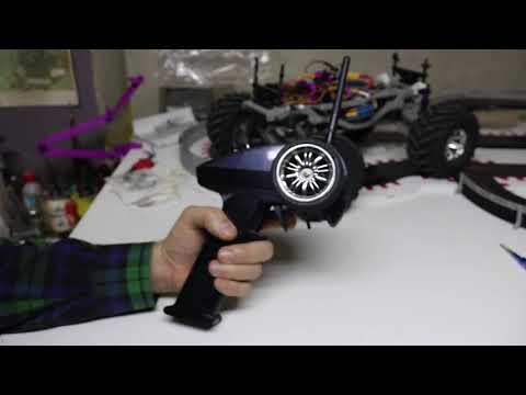
Shocks, Wheels... maybe you expected that but... also the radio 3D printed? :) Take a look!
FEATURES:
- Arduino based, very customizable
- Throttle feel like standard radios
- +-60º Steering wheel
- Muti-Channel RF thanks to nRF24L01 Modules
- Use any 1/10 On-Road RC Car Wheel or a 3D printed one for the Steering Wheel
- Works with 6xAA batteries or LiPo 18650 cell + boost-up module
- Not high level electronics, no special PCB required, most of connections with dupont cables
- Plug your Radio or receiver to your PC and re-configure many things quickly
Maybe you ask yourself why is it called "BigBoy"... My hands are quite normal-big and the radio is a little big for me... I think is the right size for my uncle, who has sausages instead of fingers... The same way, as it can be delicate if you don't solder the wires it is not recommended for kids, but you will need the passion of a big boy to get involved with this instead of buying a 17€ 2CH radio system... Anyway you are advised, this can be even cheaper than those 2CH radios but full of possibilities :)
I have been taking a look to some existing projects in the web about RC Control with Arduino and I think they reached the point of offering quite good features for a very low price, but possibilities are really quite a lot.
So the main idea here is using Arduino Nano for both transmitter and receiver. There are many tutorials out there to understand how an Arduino works with a 2.4GHz RF module, in this case the nRF24L01.
Here I let you the links to the tutos/vids I used to understand and build this radio:
CHOOSING THE RIGH ARDUINOS
I have used two different Arduino Nanos for transmitter and receiver, but you will now understand the difference.
You can find the nRF24L01 module in various formats, being some more powerful than others, more or less complicated to wire. But there is a version of Arduino Nano that includes the RF module, that is the Arduino "rf-nano"... Mines are black and you can see the "antenna" in the other extreme of the arduino than the USB port.
For the receiver I chose this small Arduino rf-nano with its integrated nRF24L01 module. That way, you only need four "dupont" cables to supply the arduino 5V and Ground from ESC and the two outcoming signals for CH1 and CH2, one for the steering and the other for the ESC.
For the Transmitter, you want as powerful as possible version of the nRF24L01 module, that is the one with external antenna and a PA (Power Amplification?) included.
IMPORTANT: To avoid having to use small transistors or resistors etc, I decided to use the Adaptor module for the big RF module which supplies 3.3V to the antenna from the 5V pin of the arduino.
LET'S TAKE IT EASY
To make the build of the radio as simple as possible, I decided to do not use a main board, so there is no need of buying a special board with the soldering involved.
Initially you will need to make a lot of tests to know the arduino, the pots, maybe some joysticks, etc... You can connect most of these elements to the arduino just using some "Dupont" cables, mostly female-female ones if you are using an Arduino with soldered pin-headers.
The Transmitter has initially 2 channels, assigned to the Throttle Trigger and the Steering wheel, but you can add more, using digital or analog inputs in the arduino.
When you read an Analog input in the arduino, you will get a value from 0 (0Volts) to 1023 (5Volts). What you do with this data is up to you.
I added in the code a few more features that can be linked to a particular Analog or Digital input, as they are:
TH_TRIM (Analog In), ST_TRIM (Analog In), ST_AMP (Analog In), TH_REV (Digital In), ST_REV (Digital In).
If you don't want to control them with an external potentiometer or switch you can always set the fixed value you want in the firmware.
But the same way, you can assign any of those pots or switches to a channel, lets imagine a pot will be sent as CH3 (1byte value, from 0 to 255) and a switch could control lights On/Off in a CH4, sending 0 when Off and 255 when On, or whatever values you want...
ARDUINO "NOOB"?
I'm not any expert in Arduino IDE, the environement I use to create and edit the firmware, but there are many examples online with cases very similar to what you need.
If you are completely un-familiar with Arduinos, I try to resume it a lot: You tweak a little a firmware (text file), upload that firmware to your arduino and see what happens but, how?
Serial.print(whatever);
One of the best ways to see it is using the Serial Monitor in the arduino IDE, it will connect to the USB (Serial COMxx) Port it is plugged and read the info is being sent from the arduino to the Serial Port. In normal working mode, you don't need to send things to serial port. This will add a lot of work to the arduino you don't need if you are not "troubleshooting".
// Commented Code
You will see part of the code after those "//"... that code won't affect the program, is just for you to read or... a way to de-activate or activate some features. For example if you un-comment (erase those //) from "// Serial.print(data.Throttle);" the Throttle value will be printed in the serial port
A WAY TO PROCEED STEP BY STEP
If you are new to many of these things, I suggest you to take it slow and think twice or more each step.
1º You will need to connect a rf-nano to the USB in your computer, install the proper driver so it is recognized as a COMxx Serial Port, Open the Arduino IDE, Select the right COM port, the right Arduino Board type, and also the right "bootloader"...
2º Maybe you want to make some of the simplest tests for an arduino, maybe generate a value and "Serial.print(it) to the serial port so you can check with the Serial Monitor, or make the on-board led in the rf-nano blink twice in a second... So the main idea for this step is, you create a very basic firmware, upload it to the arduino and confirm it works...
3º There are many examples out there about simple arduino RF communication, for example one in which the receiver blinks if correctly receiving the signal from the transmitter. I would recommend you to buy 2 RF-Nanos and 2 normal Nano V3... that way you can start your first tests with two RF-Nanos, reducing the error posibilities a lot as no wiring is needed
4º If you reached this point maybe you are ready for my code... If you feel it a little wierd initially, maybe take some other simpler example, but basically the idea is read some of the analog inputs, prepare the value, store it in a data packet and send it "trough the pipe". I bought a pair of "2 axis and a button joysticks". I started connecting just one and seeing what happened. You can connect the joystick to 2 analog inputs, or maybe just one potentiometer to one analog input... You can "Serial.print(analogRead(A0);" to see in your serial port viewer what is happening while you move the joystick or the pot.
5º At this step you should be able to read an input, adecuate the value to 1byte (from 0 to 255), assign it to a "Channel" of the packet that will be sent, receive that packet in your receiver, take the value for that channel and "Serial.print(data.Throttle);" or whatever your "Channel" is named... So, move joystick in the transmitter and confirm it is correctly received seeing it in the Serial Monitor of the arduino IDE, connected to the receiver, of course!
6º If reached this point you consider that my code is better, just start using it, but probably you could also incorporate my "ideas" to your code... I'm talking about the way I manage the variables to use TH_Trim, ST_Trim, ST_Amp, TH_Dead, etc... But anyway, more important than this, at this step you should start using a normal Arduino Nano V3 with an external nRF24L01 module with its adaptor... Use some "dupont" cables to wire it to the arduino, and try to reproduce the previous experiments when needed to see you have same functionality. If your "normal" Nanos are like mine, I needed to install different driver for my windows but also select the (old) bootloader in the arduino IDE. The same way, i felt the USB port where you connect it to the computer must have enough "Amps" to correctly boot it up with the extra antenna consumption.
7º Now you should try to fit both the arduino nano and the wired antenna with the adaptor to the 3D printed Radio Transmitter back part. If you buy the same ones than me and they come with the same measures, you should be able to fit them in the places for them in the Radio Shell... The Arduino USB port should be accesible from the back part of the radio, and the leds and reset button should be visible/accesible from the top of the radio. For this step you could need to solder Ground and 5V of the adaptor board to some "half dupont" cable instead of using a dupont cable normally because they would hit the shell... maybe you can manage the situation just bending a little the Ground and 5V pins in the adaptor, but maybe you preffer to solder there the cable.
8º If you reached this point you now are thinking... but if I'm using the 5V and GND pins to power the antenna, how do I use those pins for my potentiometers?¿?... This is the only part where a PCB would help... What is what I did?¿? I cutted some dupont female-female black/white pairs by half and created a 5V GND multi-ouput octopus... you will need at least 5 pairs of 5V/GND... those would be for arduino, antenna, Throttle Pot, Steering Pot and a last pair for "top-plate" pots and switches... I just cutted, pealed, joined, gave a point with the solder and used some electrical tape to isolate.
9º By now, you can use your radio plugged by USB to something with Amps enough, maybe a 5V usb phone charger but... what about the battery?¿? After some reading, I decided to power up the arduino from a battery using the Vin Pin, which allows 7-12V input to the arduino... The easiest way to achieve this is using 6xAA batteries, but maybe also 6xAAA using some adaptor. The reason why the radio handle is so long is those 6xAA are just in two rows. I had a 4xAA battery box from some toy. This is from where I scrapped the "Negative pole springs" and the "positive" metal plate I used. The springs should be like 10mm tall and 5mm tall when compressed by the batteries. Their diammeter should be like 8mm and the spring wire diameter like 0.6mm... Probably you will have to do some magic here... Maybe some "Clips" can be of help... or some Staples?
10º If you are in the final steps of the radio building you should have your "Throttle Trigger Assembly" done... using a 10k pot you can start closing your radio shell... be sure the pot is working before closing it. If you think something is missing in the throttle trigger for it to work you are right! Those are the springs... which springs?¿? Clipper Lighter springs... They are like 35mm long in their natural position... designed to be compressed but we will use in reverse ;) They are less than 3mm in diameter. You should be able to make the radio work with the batteries without the top front part of the radio shell assembled... The same way you will need a 10x15x4 bearing... i hope you have some spare ones from one of your cars!
11º But now you realize you can only use a little range of the potentiometer this way... not from 0 to 1023 anymore... and you are right. You will have to start using my code or copy the idea to yours... The "idea" is to create 3 variables you must know... the TH_Center, TH_Min and TH_Max... TH_Center should be the value of the pot when the throttle trigger is in the center position... how can you know this? "Serial.print(analogRead(A0)";... and observe the values the pot generates in the center, min and max positions... My code takes those values to generate the proper throttle signal, which must be 127 when idle, from 127 to 255 when you accelerate and from 127 to 0 when you brake or reverse... The same happens to the values generated by the Steering wheel... The steering wheel rotates +-60º so you will need to "Serial.print(analogRead(A1);" and look for those min and max values for your steering wheel... once you have them, you will be able to make them be near 127 when idle using TH_Trim...
12º So... you have a calibrated radio, emmiting values from 0 to 255 for the throttle and the steering, which should be exactly 127 for your throttle and near 127 for your steering when your radio is idle... Time to go with the receiver! From your ESC, take the 3wire connector, plug a male from a male-female dupont in each of the 3wire connector, preferible Brown for GND, Red for 5V and orange for signal... Then connect the female of your duponts to the arduino rf-nano to the correspondant GND, 5V and A0 pins. Just with that, you should be able to control the motor with your Throttle Trigger, you should be able to accelerate, brake, reverse, etc, depending on your ESC habilities...
13º Now you want to connect your servo to the arduino but no 5V pin free... :( I solved it using some "servo connector duplicator cable" that came with some RC Car Lights to duplicate the GND and 5V signal for the servo... You should be able to solve the rest of the puzzle with maybe 3 extra dupont cables... or you can do the same i did for the radio, create an "Octopus" of GND and 5V for as much channels as you want...
As you can see, I am just providing the "bulk" version of the top plate cover... I think this way each one will be free to use the elements (buttons, switches, pots) in the number and size they want (and are able to fit). You will have to drill the holes where you want them, maybe cut some square holes with a exacto knife... or maybe you know how to do some "booleans" with some cylinders and boxes in some 3D editing software...
COMPONENTS YOU NEED, 3D PRINTED PARTS LIST, PRINTING TIPS, ASSEMBLY ORDER and CALIBRATING THE RADIO in the "Printing Details / Tips Technical Info Section"