Update December 2022
After going to the carnivore diet, I am using my Sous Vide so much now, I sometimes need two slow cookers going at the same time. So I made another controller. During my second build, I made a couple of changes and took a few more pictures of the wiring to help others.
Cost to use: I have measured my hourly cost with a Kill-A-Watt meter for both of my slow cookers. A 270 watt 7-quart cooker and a 450 watt 10-quart cooker. It costs one US penny per hour to run either cooker at 135F. I will sous vide a 3 lbs chuck roast for up to 36 hours @ 135F. It turns out super tender.
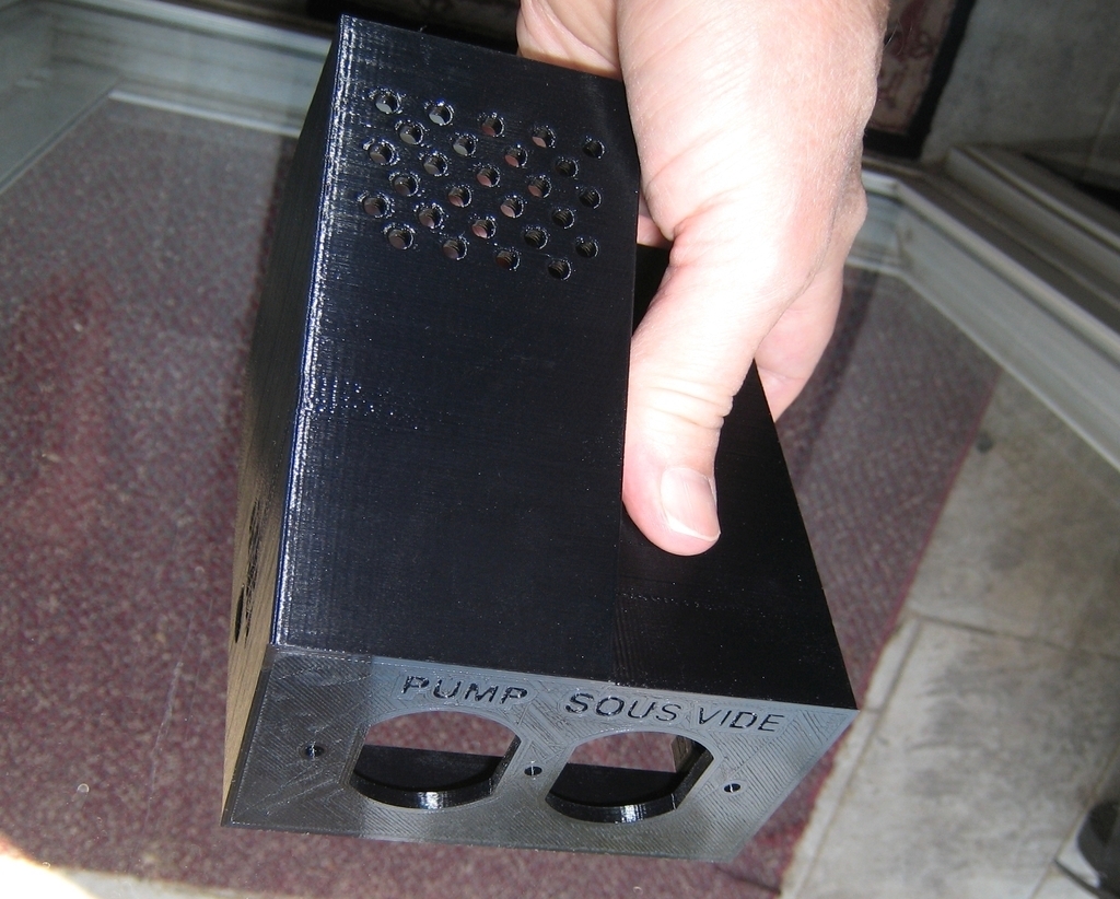
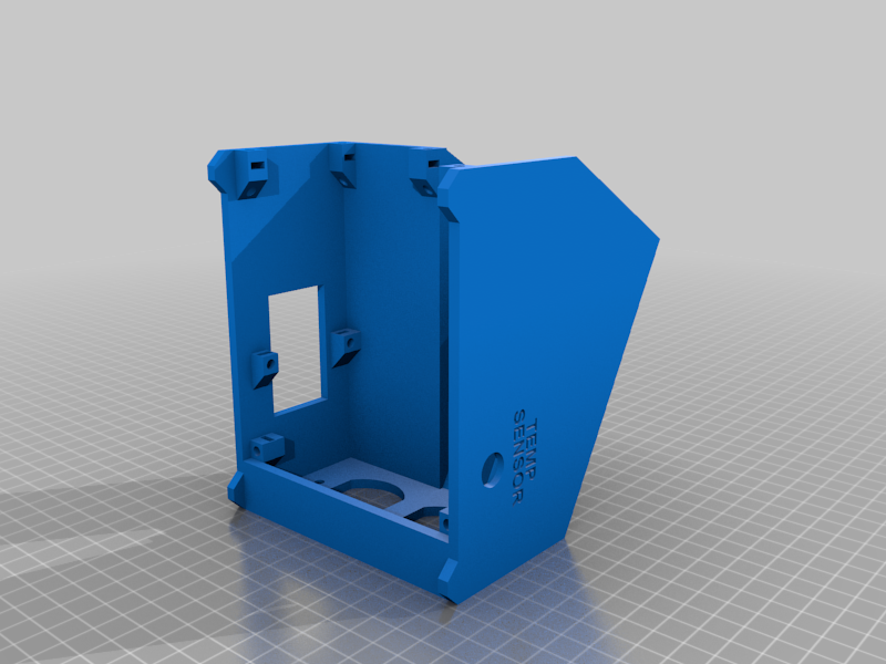
I modified the top part of the case to eliminate the center hole for the outlet. The hole exists for a wall plate and serves no other function. Plus, the cost of wall plate screws is just stupid. The two other holes secure the outlet very well.
The PID bracket requires an M3 x 20mm screw or longer in order to secure the PID to the bottom section.
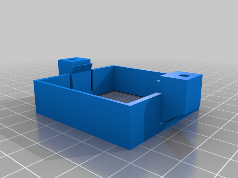
I noticed the hex nut holes in the mounting bracket for the PID were too large, allowing the nut to fall out while securing the PID to the bottom section. Now, the nuts are held securely by friction while tightening the screws against the bottom section.
Except for a couple of short pieces of wire, cut your wire lengths 15cm to 17cm in length if you are not sure about how long to cut them. This allows you to make the connections without excess straining.
Previous Text July 2019
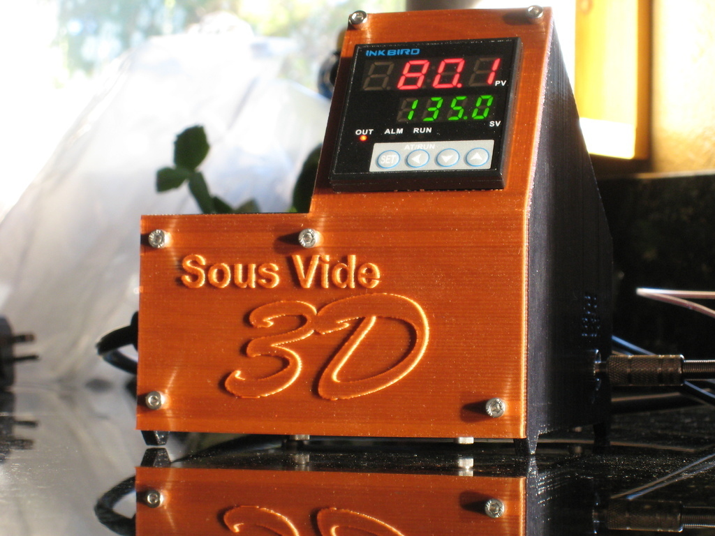
I have been exploring how to make the perfect steak, every time, with Sous Vide cooking. Sous Vide cooking guarantees your meat is never under cooked or overcooked. The Sous Vide 3D utilizes the highly accurate INKBIRD ITC-106VH PID temperature controller with intelligent proportional heat control, F & C readings and 100-240 VAC input. The angled display is easy to read, making button presses more ergonomic. It also has a small footprint.
Sous Vide 3D can handle any immersion heater or deep fryer up to 1,000 watts. My slow cookers are the type with mechanical rotating Off/Low/High switches. A model with an electronic button pad will not work.
The PID and water pump are completely silent. This silence is a nice feature for those times you want to do a long cook.
Printing the STL files is easy due to the built-in supports for the square nut retention slots that would normally require support material. The hole for the PID has a single support feature that needs to be removed once the top half is done.
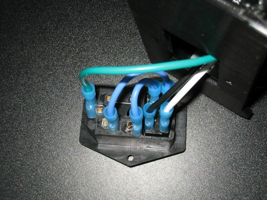
Flexible 16 gauge wire is essential for easy assembly. Silicone wire is strongly suggested. Do not use forked terminal connectors on the temperature sensor side of the PID. They stick out too far and will interfere with final assembly. Female insulated crimp connectors work well for the switch connections. Use forked non-insulated connectors for the rest of the screw type connections.
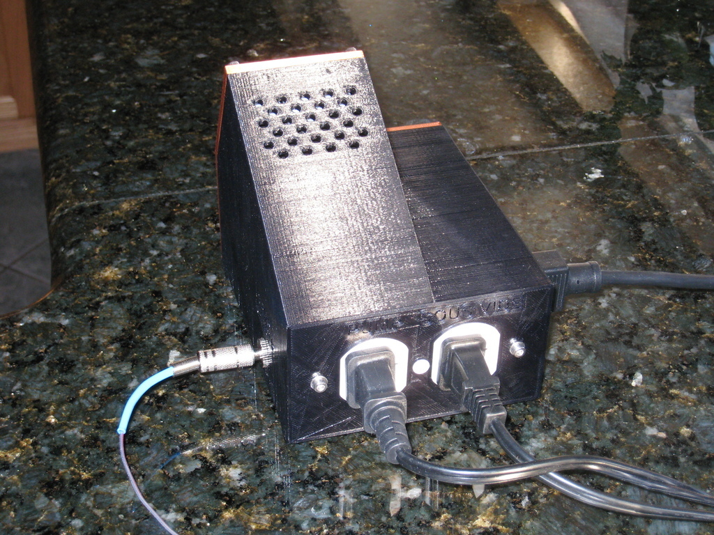
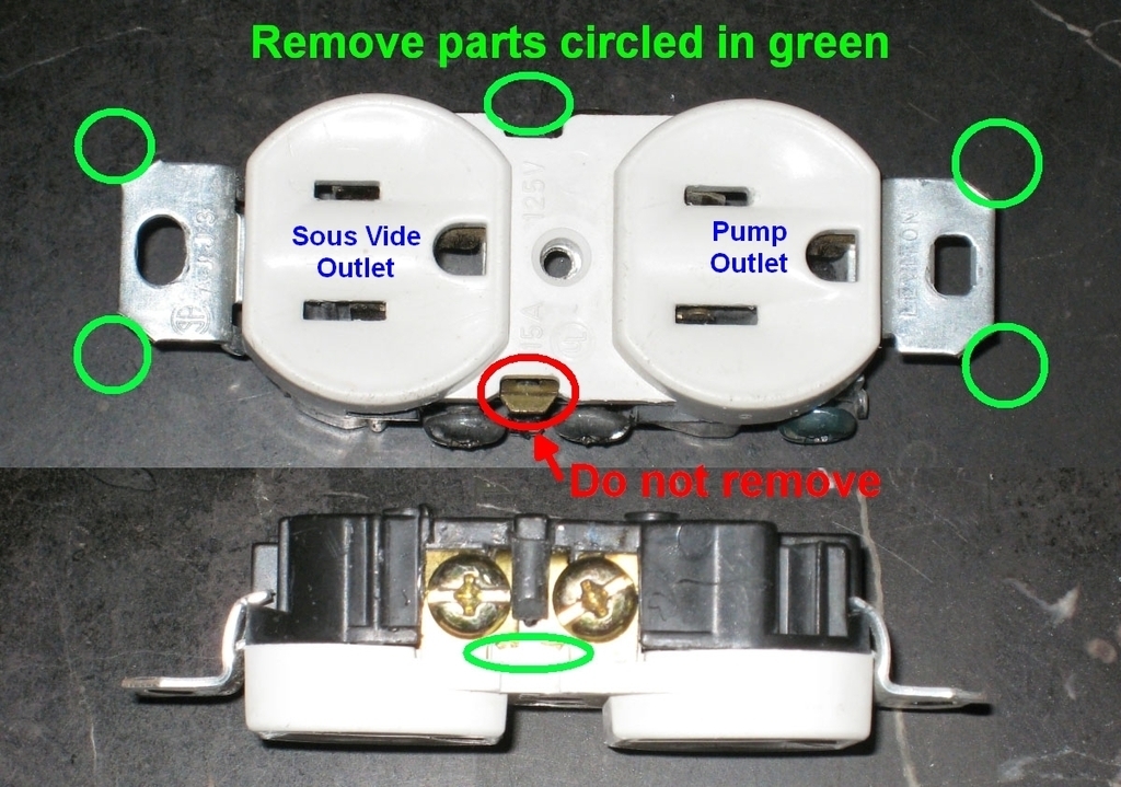
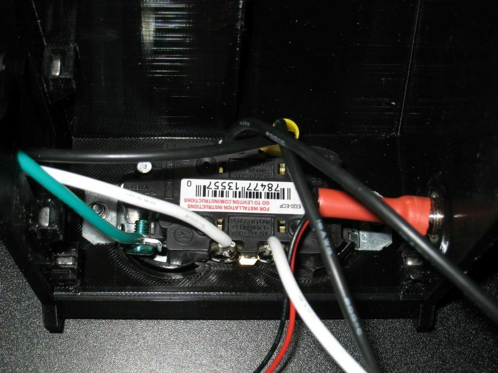
The outlet needs to be split into two independently powered outlets. To split them, you need to flex the brass piece that bridges the two sides of the brass screws until it breaks off. This breaks the electrical connection between the two screws on the Hot black-wire side of the two outlets. You should leave the piece connecting the two silver screws on the Neutral white-wire side of the outlets. Breaking the little brass bridge on the hot side of the duplex outlet allows one outlet to provide power full time to a tiny water circulation pump. The PID controls the power to the other outlet for your Sous Vide device (slow cooker). See included image.
To save space, I removed the outlet's four "ears" with the screw holes on each end of the outlet. Flex them until they break off.
Assembly is frustration free. Each square nut is press fitted into a slot where it becomes permanently captured. This allows you to assemble the two halves without the nuts falling out of position. All the holes are in perfect alignment. Put the nuts into the slots before any other assembly steps.
The PT100 waterproof temp sensor PID setting is type 'PE'.
Shopping List:
* INKBIRD ITC-106VH Digital PID Kit w-25A SSR and PT100 Temp Sensor
* 120V DUPLEX RECEPTACLE WALL OUTLET
* Mini AC 110V/220V 3W Submersible Water Pump w-Flow Adjuster
* 2.5mm x 5.5mm DC Power Female Jack PC Panel Mount Socket Connector
* 5.5mm * 2.5mm DC Power Male Plug Jack
* 3 Pin IEC320 C14 AC Inlet Male Plug Power Socket With Fuse Lighted Switch 10A 250V ST-30
* M3 Square Nuts (10)
* M3 x 12mm Socket Head Cap Screws (14)
* M3 x 20mm (2) Screws & Hex Nuts for the PID Bracket (or longer)
* Miscellaneous M3 Screws & Nuts
* 16awg Silicone Electrical Wire Cable 6 Colors (5ft Each) Tinned Copper
* Fully Insulated Female Spade Terminal Crimp Connectors for Power Switch (7)
* 3-Pin Power Cord for On/Off Switch - PC Power Cord Style
Order of Assembly December 2022
* Slide the 10 square nuts in the slots in the top section. Make sure they are fully seated with the threads visible through the holes. Check that they don't fall out. If one does, try a different nut, or a little glue stick that plugs the slot with the nut inside.
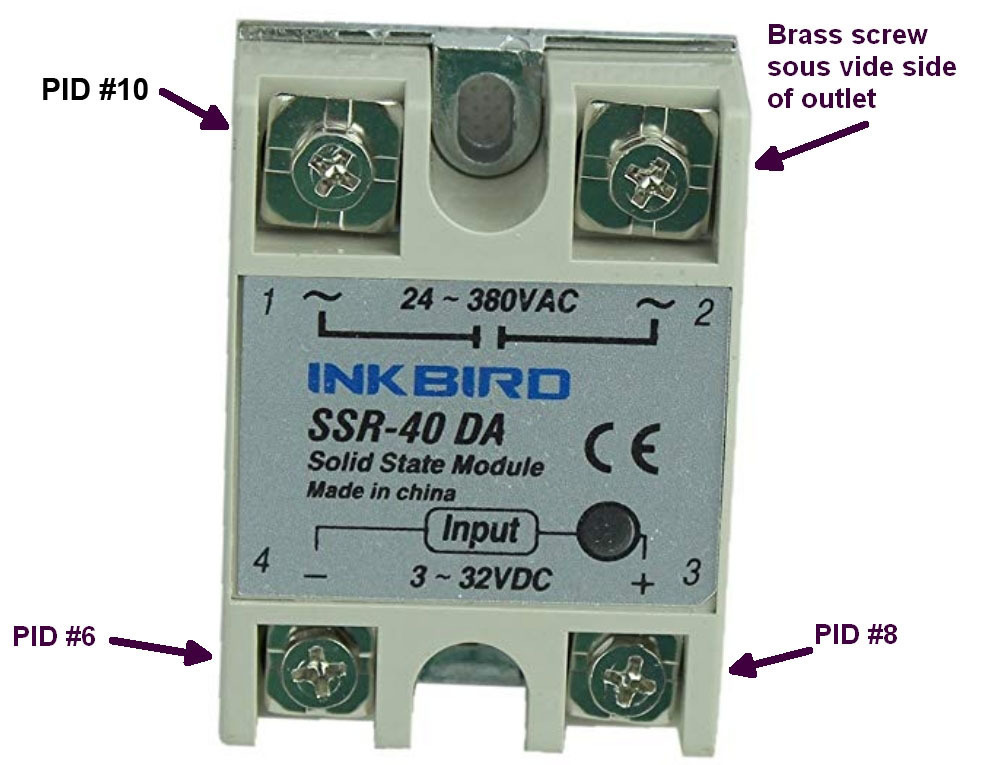
* Mount the SSR to bottom section.
* Attach wires to terminals 3 & 4 of input side of the SSR.
* Attach the two short jumper wires to the switch.
* Modify the outlet per the instructions.
* Attach all wires to the modified outlet.
* Secure the outlet to the top section with two screws and nuts. A long nose locking pliers is helpful for getting the nuts on the screws.
* Remove the support piece from the PID hole with a filament flush cutter and slide the PID into the bottom section. Take care to not stress and break the layers in this section. It's much stronger after final assembly.
* Assemble the screws and nuts on the PID mounting bracket.
* Slide the PID bracket onto the PID and slightly tighten the screws against the inside bottom section. Just tight enough so the PID doesn't rattle around.
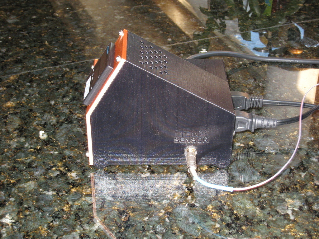
* Solder the sensor wires onto the male barrel connector. Center pin + (red).
* Solder internal PID wires onto the female barrel jack and mount in the top section. Center pin + (red).
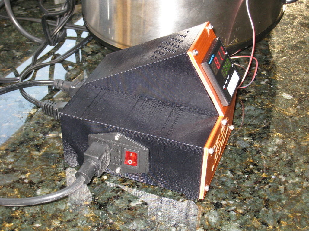
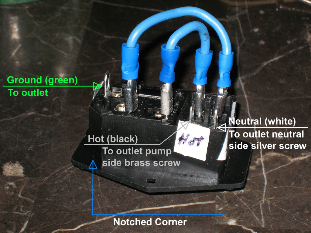
* Slip the hot, neutral and ground wires from the outlet through the switch hole and connect them to the switch. Let the switch dangle for now.
* Connect all remaining wires, including the temp sensor jumper wire on PID #4 and #5.
* Double check all connections have been run to the correct location.
* Secure the top and bottom sections together.
* Mount the switch.
* Connect the temp sensor, water pump, slow cooker and power cord. Verify the pump flow gate is wide open.
* Set slow cooker to Hi.
* Fill your slow cooker about 2/3 full of water.
* Power it on and go through the PID setup. A YouTuber called Barley and Hops Brewing has a very helpful video called, Settings for the InkBird 106VH controller. It's a good place to start. But I recommend you do the "self-tuning mode" procedure after you have completed his tutorial. His step 4 PID settings are not ideal for your sous vide slow cooker. The step #2 oP self-tuning procedure will automatically determine your best settings and write the new values to the controller. Auto-tuning will stop flashing when it has completed.
This thing has gone through many revisions to ensure everything fits perfectly. Many, many hours of design and many print models were required to bring it to this point. If you make one for yourself, a picture would be greatly appreciated. And of course, a tip would help me recover some of my filament costs as well.
Once your Sous Vide 3D is complete, you will have an accurate, easy to use device that matches the quality of Sous Vide machines costing far more. Plus, if one part goes bad, you will know how to repair it as opposed to throwing the whole thing away.
Working with 120 Volts AC can harm and kill you. By building this thing, you agree to accept 100% responsibility for any personal injury or property damage you may suffer.
-VegasGuy
:format(webp)/https://fbi.cults3d.com/uploaders/30142993/illustration-file/76c27808-0a5e-4c46-93b0-23e3cf3f2d64/IMG_4214.JPG)


/https://preview3d-images.cults3d.com/0w20z4aor4yn10pppuuotl8imj0o)
/https://preview3d-images.cults3d.com/i3pzuxnqzuvesoh80zjmupbkafjn)
/https://preview3d-images.cults3d.com/2wlouuh92c9ul4x4t2nz75pc2j1e)


