Skip to content

Anycubic i3 Mega Z-axis stabilizer

Advertising
Advertising
?
Creation quality: 0.0/5 (0 votes)
Evaluation of members on the printability, utility, level of detail, etc.

  • 396 views
  • 3 downloads
  • 1 collection

License
3D design format
STL Folder details Close
  • M1.stl
  • M2.stl
  • M3.stl
  • M4.stl

Learn more about the formats

Publication date 2023-11-02 at 19:29
Design number 1553876

3D printer file info

3D model description

This stabilizer prevents the Z-axis from oscillating during printing, which results in an unsightly offset of the print layers as the print height or print speed increases.

Due to the stabilizer, the oscillation of the Z-axis is very strongly damped and the remaining small residual oscillation is also passed on to the Y- and X-axes, which means that all axes are always at a 90Β° angle to each other during printing.

This also enables higher print speeds, jerk and acceleration values for X/Y while maintaining the same print quality.

In addition, this stabilizer allows the Z-axis to be angled accurately.

The following is required for installation:

printed parts M1-M4 (infill 100%)


4 x M6 x 25mm socket head cap screws + corresponding tap and pilot bit


4 x M6 washers (not body washers)


8 x M4 x 20mm socket head cap screws


8 x M4 nut


2 x 8 x 330mm linear shaft or e.g. threaded rod


Sandpaper P400

Installation:

Level bearing surfaces of brackets M1 to M4 with sandpaper and provide linear shafts from the ends at 5, 15 and 25mm with a circumferential notch (e.g. with angle grinder). The latter serves to hold the very smooth linear shafts firmly.

Provide bracket M1 and M4 with 2 M4 screws and nut each.

Connect bracket M1 and M4 with linear shaft and tighten M4 screws slightly. The distance between the two brackets must be approximately 255 mm.

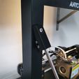
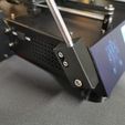
Align brackets (M1 top/M4 bottom) with the bearing surfaces on the unit so that the bearing surfaces are completely flat. The position of the entire stabilizer thus results all by itself. (see pictures below)

Place mark for the holes on the printer housing.

Pre-drill holes for the M6 threads and cut threads.

Fasten stabilizer with the M6 screws incl. washers. Mark the screw on the upper bracket (M1) on the rear and then shorten it when removed so that it protrudes a maximum of 2mm on the rear (see picture below).

Repeat point 2. - 7. with the right side.

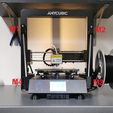
M1 = M2 / M4 = M3 Align Z-axis and tighten all screws securely

3D printing settings

Resolution: 0.2

Infill: 100%

Advertising


Page translated by automatic translation. See the original version.
Issue with this design? Report a problem.

Would you like to support Cults?

You like Cults and you want to help us continue the adventure independently? Please note that we are a small team of 3 people, therefore it is very simple to support us to maintain the activity and create future developments. Here are 4 solutions accessible to all:

  • ADVERTISING: Disable your banner blocker (AdBlock, …) and click on our banner ads.

  • AFFILIATION: Make your purchases online by clicking on our affiliate links here Amazon.

  • DONATE: If you want, you can make a donation via Ko-Fi πŸ’œ.

  • WORD OF MOUTH: Invite your friends to come, discover the platform and the magnificent 3D files shared by the community!


Sharing and downloading on Cults3D guarantees that designs remain in makers community hands! And not in the hands of the 3D printing or software giants who own the competing platforms and exploit the designs for their own commercial interests.

Cults3D is an independent, self-financed site that is not accountable to any investor or brand. Almost all of the site's revenues are paid back to the platform's makers. The content published on the site serves only the interests of its authors and not those of 3D printer brands who also wish to control the 3D modeling market.

100% secure payment by credit card, PayPal, Apple Pay, Google Pay, etc.
View all payment options.