Improved Flow ratio Calibration v3
Improved Flow ratio Calibration v3


Print Profile(1)

Description
Here's improved flow calibration compared to Orca or Bambu Studio. This is the third iteration from the original models: Improved flow ratio (extrusion multiplier) calibration v1 by jimcorner - MakerWorld, Improved Flow Calibration v2 by jimcorner - MakerWorld. The goal is to make flow rate calibration as straightforward as possible with a repeatable and clear standard.
Please download the 3mf file and slice it yourself in Orca, the 3mf does not work with Bambu Studio bc it doesn't support per object flow ratio setting! As a result, the print profiles uploaded by other people here likely won't work.
Why I upload this:
- the default flow calibration is bad at determining which flow rate has the smoothest surface with the monotonic top infill pattern, especially for white filaments. The result is often subjective.
- There are too many test pieces to keep track of.
What's improved compared with Orca/Bambu Studio:
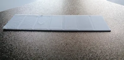
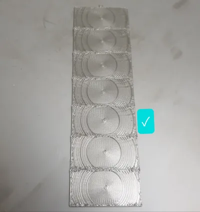
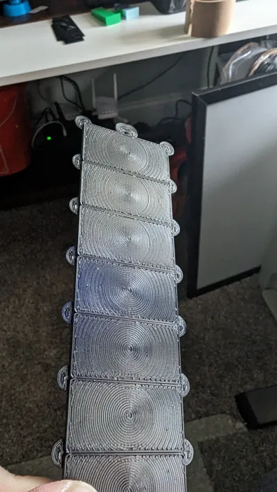
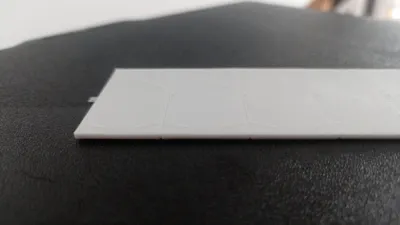
- The result is now much more definitive and clear, I can even capture it with my phone camera as shown in the photos
- The top surface is Archimedean Chords pattern instead of monotonic, and line width is increased to 0.6mm, making it much easier to tell which flow rate is the best and take out the guess work. All other settings are exactly the same as Orca Slicer/Bambu Studio flow ratio calibration, so the calibration print is set up similar to originally intended.
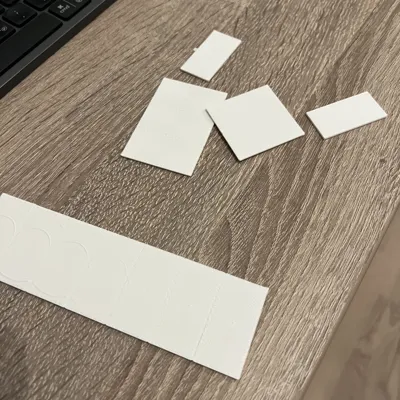
- The test pieces are put together as one piece, instead of 10 smaller pieces that tends to clutter up space and easy to be lost.
How to use this test:
Prerequisite: open the 3mf file in orca slicer, and select the filament you want to calibrate.
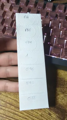
- Pass 1: change the flow ratio in the filament tab to 1.0. Once that's set correctly, the flow ratio of the 7 pieces are: 1.12, 1.08, 1.04, 1, 0.96, 0.92, 0.88. Slice plate 1 named “rough”, and print. Find the flow ratio right before the raised right half circle appears, as flow_rate_rough. Usually this number is around 1.0, and if you know the ballpark number, you can use that value and skip this step.
- Pass 2: change the flow ratio in the filament tab to flow_rate_rough from pass 1. Slice and print the second plate named “fine”. Going from bottom to top, find the second flow ratio that gives the raised right half circle, as captured in the photos above. This is the optimal value to use for future printing.
- Optional: If there are fewer than two pieces with the raised right half circle, repeat pass 2 with increased value for flow_rate_rough.
Notes: in pass 2, the flow ratio of the 7 pieces are: [1.03*flow_rate_rough, 1.02*flow_rate_rough, 1.01*flow_rate_rough, 1*flow_rate_rough, 0.99*flow_rate_rough, 0.98*flow_rate_rough, 0.97*flow_rate_rough]. You can also see this in the per object setting → quality → flow ratio. The actual flow ratio when printing is the filament flow ratio value set in the filament tab * the scalar set in the per object flow ratio scalar.
Why/how well this works:
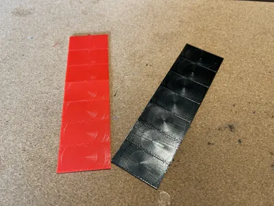
The optimal flow ratio should make the lines squish into each other to fill the gaps, but they should not be squished together too much because severe over extrusion creates ridges and uneven surfaces. The goal is to find the optimal flow ratio for the right amount of squishiness between the extrusion lines. Here the Archimedean Chords pattern and larger line width of 0.6 amplify the effect of between-line-squishiness by inspecting the raised right half circle. As the flow rate goes up from the bottom to the top of the test pieces, the optimal flow rate would be somewhere when the raised right half circles start to appear as it means the lines start to get squished together. To account for the test error bar and filament diameter variation, I choose the second visible raised right half circle for the optimal flow ratio. In my testing this gives a smooth top surface in my normal prints with minimal/no signs of over-extrusion. And the results I get is consistent with the values provided by the manufacturers as well, which gives me confidence as this method converges with manufacturers suggestions. For example, in the photos, the red filament is polylite pla which has 0.95 flow ratio recommended by polymaker, and my test gives 0.95. The white filament is sunlu pla+ has recommended 0.98 flow ratio and my test gives 0.98.
Comment & Rating (59)