Easy Beest
Easy Beest


Print Profile(2)

Description

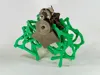
This is a simplified version of Theo Jansen's iconic Strandbeest kinetic sculpture/creature. Most of the 3D printable Strandbeest models I've seen involve a bajillion pieces, but this version simplifies things by 1) having the leg assemblies mostly print-in-place pre-assembled, and 2) replacing a complex crankshaft assembly with a geared drive system. The gears aren't quite in keeping with the original Strandbeest aesthetic, but they sure are easier to assemble.
This model is also fairly modular in that you can add as many leg units as you like, and you can use it with the motor drive (as shown), or there are also parts for just hand cranking the legs with a knob.
If printing the motorized version shown you will need the following additional parts:
1 motor (https://www.amazon.com/Driver-Engine-HN-GH12-1035Y-Motor-Reduction/dp/B0CFZ9KYKJ)
1 battery box (https://www.pololu.com/product/1152)
3 AA batteries
Printing
All parts are printed in PLA with 0.2mm layers, 3 perimeters and 15% infill. The only modification from standard print settings is that the posts on the various plates need to be printed more slowly so that you get complete layer adhesion. I did the by setting the small perimeter threshold to 20mm and then setting the small perimeter print speed to 40mm/s.
Important: Before printing the all of the parts, I strongly recommend printing 2 of the test pegs to check the fit, as the entire structure relies on the integrity of getting the right press fit. The pegs should stack together with a medium press fit (snug, but not impossible to pull apart). If the fit is too tight or too loose, you can adjust the X-Y contour compensation to get the right fit. Once you print all of your plates, try press fitting them all together into a stack, without the legs or gears. You can then use the included pry bar to gently pry them apart before beginning the complete assembly.
What to print:
You'll see in the first plate of the 3MF file that 2 leg units ,the base, 40t gear, 15t gear, and clip are grouped together. You'll want to print as many sets of this plate as you want legs. In the case of the motorized beest shown, you'll print 4 of these plates.
The second plate contains all the parts that you only need one of per beest. Note that if you are printing a non-motorized version, you can skip the battery plate, motor plate, drive gear and drive pinion and instead print the one of the end plates and the knob.
Lastly, if you want to add more legs, you'll need to scale the shaft in just the X direction to increase the length for however many legs you want. (I wouldn't suggest more than 5 legs for the motorized version as the motor may not have enough power.)
Assembly
First some general assembly notes. After gently breaking loose the legs from their print-in-place configuration, you should lightly sand the underside of the the ends of the free-floating links that are a little raggedy. You should also lightly sand the face of the 40t gear and along the length of the shaft. I recommend adding a tiny bit of light grease or vaseline to the gear teeth and sliding surfaces.
 | First solder the wires from the battery box to the motor. The polarity doesn't really matter. |
 | Press the 15t drive gear onto the motor shaft. Note that if you flip the gear one way or the other the gear will press slightly further down the shaft. Use this orientation. |
 | Start by pushing the shaft up through the back side of one of the base plates. Place one of the 40t gears over the center post. Push the 15t gear onto the shaft and down so it meshes with the 40t gear. Slide one of the clips over the shaft until it presses against the 15t gear. Spin the shaft to make sure everything runs smoothly. |
 | Assemble one of the leg units onto the left side of the base plate as shown. Note that the upper free link of the the leg goes over the gear post first, followed by the lower free link. |
 | Take another leg unit and flip it over and assemble it to the right side of the base plate. Note carefully the order in which all of the free links are stacked onto the gear post. |
 | One of the trickier parts of the assembly is keeping the links in place as you press the next base plate on top of the first. I've found that laying a flat steel ruler or hacksaw blade (something thin and stiff) across the top of the gear post and link ends will keep them in place, as you press the next plate on top. |
 | Press the next base plate on top until it contacts your flat ruler. Pull the ruler out and then give all 5 posts a final push to make sure they are fully seated. Spin the shaft to make sure everything runs smoothly.
Note that before proceeding, you should spin the shaft to position the legs so that the feet are almost touching. This is important for subsequently setting the proper phase between all the legs. |
 | Place the next 40t gear onto the center post, making sure the gear post is in the 6 o'clock position as shown. (Make sure the first set of legs haven't moved from the position shown above.) Then add the 15t gear and the clip. |
 | Assemble the next set of legs as you did with the first set. |
 | Slide the battery plate over the shaft and onto the second plate, again using a flat steel ruler to keep the link ends from flopping off the gear post.
If building a non-motorized version, skip this step. |
 | Add the next base plate, 40t gear, 15t gear and clip. Note for this 3rd leg set, the gear should be in the 3 o'clock position. |
 | Assemble the 3rd set of legs as before. |
 | Add the 4th base plate, 40t gear, 15t gear and clip. Note that the gear post for this 4th set of legs should be in the 9 o'clock position. |
 | Add the 4th set of legs and then cap it off with the motor plate. |
 | Slip the battery box into the tray in the middle of the beest. The switch should be oriented to fit into the notch on the battery plate. The box is just held in with gravity – to remove it, just tilt it out again.
If building a on-motorized version, skip to the last step. |
 | Insert the motor into the clip on the top of the motor plate, and orient it so that the motor shaft is as high as possible. |
 | Slide the drive gear onto the main shaft. Rotate the motor so that the drive pinion engages the drive gear. Add a zip tie around the clip and gearhead to help lock the motor in place. Finally add one last clip to the end of the main shaft.
If building a non-motorized version, add the knob to the main shaft, followed by one last clip. |
Operation
Hold the unit by the motor (it's easy to get your fingers trapped in the leg linkages) and turn on the switch on the battery box. The switch is not in a very convenient location for this application, so you may need to use the tip of a pencil to flick the switch on. All the legs should start moving. If you've maintained the proper phasing of the legs during assembly, you should be able to set it down on a smooth flat surface and have it not fall over, and even better yet, start walking.
Due to the nature of the highly non-linear linkage used for the legs, all of the feet in contact with the ground aren't going to be moving at exactly the same rate. Therefore, you need to run this on a smooth table or countertop that allows the feet to slide a little bit relative to one another. Running this on a cloth surface will cause the legs to bind up and it'll probably fall over or stall. (Do not let the motor run stalled!) In fact, I believe this is why it is a “strand” (beach in Dutch) beest, rather than, say, a street beest – the sand can accommodate the foot speed variations while also providing some resistance for driving the legs.


