USS Monitor Model with Hybrid Power Plant
Description
PDFA great toy for the bathtub, pool, or even the creek in the back yard.
I had previously built boat models that used a twisted rubber band powering the propeller for propulsion but was disappointed in the performance. A long time was spent winding the rubber band in comparison with the time the model spent moving through the water. So, the first concept in this design was to use a gear train to wind the rubber band faster. Then in a stroke of inspiration, a spring could be added in the gear train to store additional energy. Hence, a hybrid power plant.
Additional Material Needs
5 - M3x10 cap head screws
4 - M3x40 cap head screws
9 - M3 hex nuts
2.5mm Ball-End Hex Screwdriver will be useful (McMaster-Carr part number 5497A53).
Long nose or bent nose pliers can be helpful in placing nuts and screws and shaping paper clips.
1/16” (1.5mm) drill
Large paper clip
Super glue
Vaseline or lubricating grease
Printing
I sliced everything with a 0.25mm Z-step and use 20% hexagonal fill. Print everything with support. The rudder slot in the hull is designed with 45 degree top slopes to convince the slicer that support isn’t needed there.
Platter Contents
In platter-1 the motor cover support posts and long vertical shafts have addition printed disposable columns to keep the extruder moving/occupied so plastic can cool before the next layer. The 8 tooth bevel gear has a support ring added at the bottom of the teeth that needs to be cut away after printing (I found the gear teeth printed cleaner using this support than with the slic3r generated version). The support on the bottom of the ratchet disc can be separated using a knife blade BUT, I found that first scoring the support material from the center axle to the rim on two sides prevented the short axle stub from breaking off while removing the support. There will be support to be removed from the bottom of the 16 tooth bevel gear and the brackets that support it. The 16 tooth bevel gear should turn freely in the brackets.
Platter-2 contains gears etc. Since one of the 33 tooth spur gears has a pin that will connect to the spring, a couple of additional disposable printing posts are included to keep the extruder occupied so it won’t concentrate exclusively on that single gear pin. Two bushings are included for the ratchet pivot since I generally lose one during assembly. After printing check that the combination 12-tooth/33-tooth gears turn smoothly on the ratchet disc axle and on the 8-tooth bevel gear axle.
Platter-3 contains the rudder, the rudder flap, the propeller, and the prop holding lever (the prop holding lever will be useful while winding the rubber band). The rudder will have support to trim off before the rudder flap may be snapped in place.
Platter-4 contains the gun turret, a spare winding key, a fixed key for winding using the turret, and snap springs to hold that key in place.
Platter-5 is the spring motor base that’s contained as part of the monitor hull. This is included in case anyone may wish to incorporate this motor into a remix for a different application. You won’t need to print this piece unless you’re constructing a stand-alone motor.
Platter-6, (the monitor hull) can be rotated 45 degrees to fit on your print bed. The hull contains a number of vent holes. Because, the motor space needs to flood so the model floats low in the water (like the original ironclad). And, when printed with ABS filament, the holes provide stress relief to avoid de-lamination of the print layers. The hull shape below the water line contains some poetic license that differs from the original ship for print-ability and to minimize de-lamination. I printed with ABS and used a couple drops of acetone to seal the minor de-lamination that occurred.
Assembly
Using the 1/16” (1.5mm) drill clean out the printed holes in the propeller and rudder frame. Note: the hole in the rudder frame is angled down a couple degrees to account for the rubber band pull in that direction. Then drill (clean out) the hole in the end of the ratchet disc axle. That hole is about 35mm deep and is intended to reinforce that shaft.
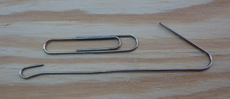
Straighten the large paper clip and put a kink next to the small loop so the rubber band will pull along the axis. Then cut it about 50mm from the small loop. Notice that I’ve also cut about 10mm off from the small loop.
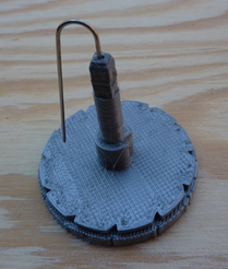
Fill the hole you drilled in the ratchet disc axle with super glue. Work the glue to the bottom of the hole using the end of the paper clip then let it cure. This is reinforcement in the winding shaft for the motor. When the glue has polymerized clip off the external portion of the paper clip.
Thread the straightened paper clip through the rudder frame and the propeller. Note: the small notch next to the hole in the propeller should be where the paper clip pokes out. Then bend about 5mm of the paper clip at a right angle so it fits into the notch to drive the propeller.
Finally, snap the rudder paddle into place.
Seat the 9 nuts into the nut-traps in the bottom of the hull. I found that pulling the nuts into place using an M3x10 cap screw and the ball-end hex screwdriver worked well. Insert the M3x10 screw from the other side, start a nut by hand and pull it snugly into the trap with the screwdriver making sure that it lines up with the trap orientation. Then back out the screw.
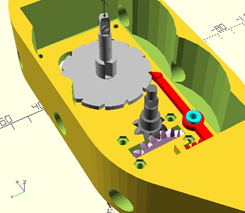
Next attach the ratchet and bushing in the bottom of the motor cavity as shown using an M3x10 cap screw.

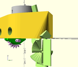
Make sure that all support material has been removed from the 16 tooth bevel gear and the support brackets and that it turns smoothly in the bearings. Smear some grease on the bearing surfaces and around the corresponding bracket surfaces. Then attach the 16 tooth bevel gear and the support brackets to the bottom of the hull using 4 M3x10 cap screws.
Now smear some grease/Vaseline in the axle bearing holes and on the bottom of the axles. Install the 8-tooth bevel gear/axle and the ratchet disc/axle. They should turn freely with little drag.
Drop the spring onto the ratchet disc shaft. Note: it’s keyed to install in only one direction. You may need to flip it over to fit.

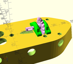
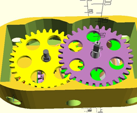
Lubricate the gear centers and two shafts where they slide. Now slide the 33 tooth spur gear with the post onto the ratchet disc axle, making sure that the post slides into the hole in the end of the spring.

A combination 12-tooth/33-tooth gear slides onto the 8-tooth bevel gear axle with the 12 tooth gear down.

And a combination 12-tooth/33-tooth gear is slid onto the ratchet disc axle again with the 12 tooth gear down.
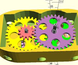
Finally the 12 tooth spur gear is slid onto the square key on the 8-tooth bevel gear axle.
Lubricate the bearing holes and install the motor top using 4 M3x40 long cap head screws.
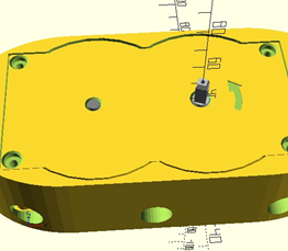
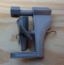
There are a couple options for attaching the winding key and turret. The key shown just slides onto the ratchet disc shaft and will slide into the recesses in the turret (so they are easily separated). However, on the print platter with the turret there is another winding key with spring loaded pins that can be installed and will snap into indentations in the top of ratchet disc shaft (difficult to remove). Either one of the winding keys may be glued into the bottom of the turret (if desired).


The rudder frame slides into the diamond channel in the rear of the hull.

The Prop holding lever snaps onto the round section of the rudder frame to hold it in place. The longer blocking piece goes on the left (i.e. to port). I found that working the lever back and forth while pushing down on it helped to seat it properly. Then pushing the top of the lever to the left (i.e. to port) blocks the propeller from turning while winding the rubber band and the internal spring. Pushing the top of the lever to the right (i.e. to starboard) releases the prop.
Now to break-in/polish/smooth the moving surfaces wind the motor using the key. If winding doesn’t spin the 16-tooth bevel gear on the bottom, give the gear a little push. Repeat this step until the 16-tooth bevel gear spins smoothly as you wind the motor. This process is polishing any roughness on the gear surfaces.
Thread a rubber band through the slot in the 16 tooth bevel gear shaft and connect the ends to the loop you formed in the paper clip. I found a pair of number 12 rubber bands (the same size as the rubber band gun uses) connected via a slip knot so they were in parallel had about the right amount of torque when twisted.
Block the prop and wind the rubber band. (i.e. push the prop holding lever to the left.) As the rubber band gets more twists the internal spring will also be wound. Launch your ironclad and switch the prop holding lever to starboard.
Tags
Model origin
The author marked this model as their own original creation.


