Linear Actuator with 3D Printed Ball Screw
Linear Actuator with 3D Printed Ball Screw


Print Profile(1)
Description
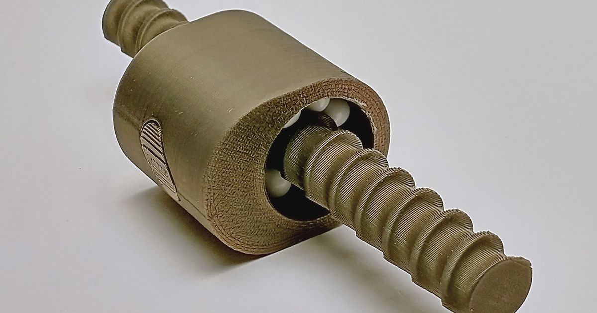
This linear actuator features an integral 3D printed ball screw for smooth, efficient operation. The ball screw and nut from my previous model are integrated into the moving actuator tube. It uses 28 6mm dia. airsoft BB's for bearing balls. The stroke is 150mm. I've tested it with a short (34mm long) NEMA 17 and can get about 10kgf. The pitch of the screw is 6.5mm.
Just a few additional screw parts are needed:
- 5 M3 x 5mm screws
- 2 M3 x 12MM screws
- 2 M3 nuts
- 2 M4 x 12mm screws for the base yoke
- 1 M8 x 35mm bolt for the end yoke
Printing
I printed all parts in PLA with 0.2mm layers. The only part that might need supports is the base yoke on the inside of the big holes. When printing the screw you need a near perfect first layer and is best done on a printer with mesh bed levelling.
Note that the motor end of the screw has a horizontal slit with a built-in support. Use a thin blade to remove this support.
Assembly
First follow the instructions here for assembling the ball screw at the end of the nut tube. Position the ball nut to the middle of the screw. Insert the nut tube into the motor tube so that the end of the screw protrudes out of the back end of the motor tube.
Next, insert the motor shaft into the end of the screw, leaving about a 1.5mm gap between the end of the screw and the face of the motor. Insert M3 nuts into the clamp at the end of the screw and then insert and tighten the 2 M3 x 12mm screws.
Slide the motor up to the end of the motor tube and secure with 4 of the M3 x 5mm screws. Insert the last M3 x 5mm screw into the hole in the other end of the motor tube so that it protrudes into the slot in the nut tube. This acts as a stop to keep the ball nut from running off the end of the ball screw.
Finally, assemble the yokes at either end of the actuator. The base yoke uses the little stud spacers on either side that are secured with the M4 screws. The end yoke is held in place with the 8mm bolt and nut.
Once assembled, the actuator should be back-drivable so that you can test the range of motion. Then just connect it up to your favorite stepper motor controller.