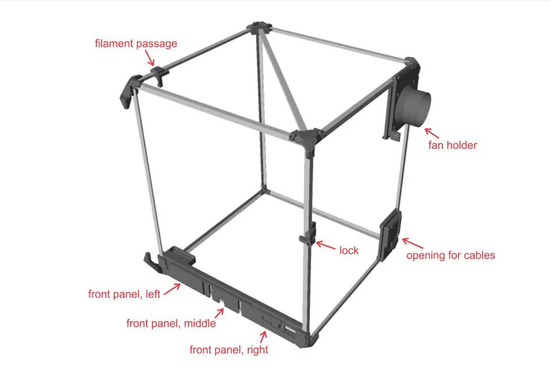
DIY enclosure for Prusa i3 or similar printers
Description
PDFThe primary purpose of this enclosure is ventilation of toxic fumes from materials other than PLA, and it's not specially optimized for increasing ambient temperature (it's quite a large volume of air inside so it's difficult to reach high temperatures using passive heating from bed), although it does help prevent sudden changes of air temperature. This means that the printer won't need any special preparations to be used in enclosure (like reprinting parts with temperature resistant material, relocating PSU, ...). To optimize for higher ambient temperature, the enclosure would need to be made lower (with the filament spool placed somewhere outside) and maybe some other changes (like better insulating).
The enclosure is designed for Prusa MK2, but can be used for MK3 & MK4 and any other similar printer. In any case, the LCD screen must be detached and placed outside the enclosure. The front panel opening is primarily designed for Prusa MK2, but I've made a variant for MK4 as well (for LCD screen "Version A", as this is what I have), see step 7b below.
I've placed the ventilation fan on the enclosure, as it was simpler for me (see step 6 below), but this position is not optimal - It would be better if the fan is placed on the window (on the other end of ventilation).
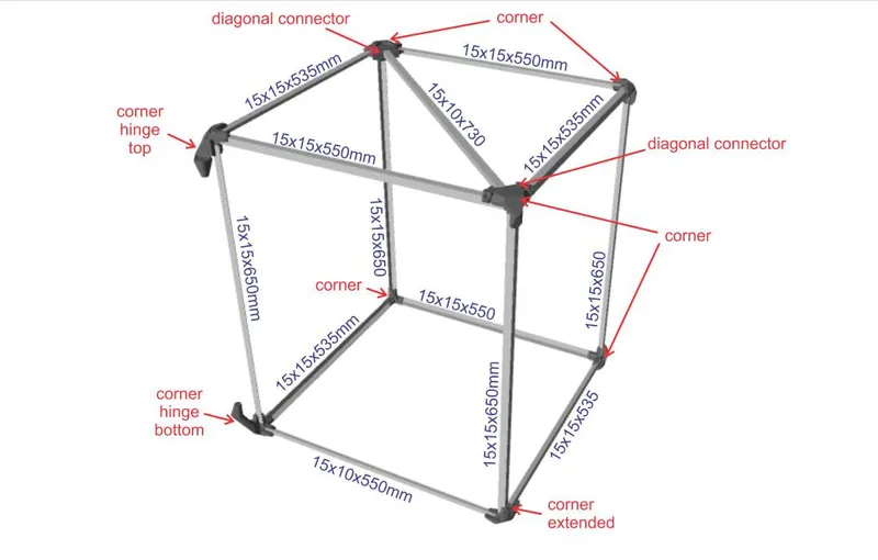
The provided dimensions of the enclosure are adapted for my setup, and can be adjusted by preference. Just make sure to adjust all the dimensions accordingly (main frame, door, aluminium profiles & plastic sheets). If you want the fan to be on the other side, just mirror the "fan holder" in the slicer, but since the top diagonal on the frame must be flipped as well, also mirror the "diagonal connector". If you want the door to open the other way, mirror "corner hinge bottom", "corner hinge top", "door hinge bottom", "door hinge top", "lock" and "door handle". Also, you would need to adapt the shape of plastic sheets to match your configuration of attachments on the frame.
Required material
- M3x8 23pcs (in most cases M3x6 can be used instead)
- M3x12 4pcs
- M3x10 (for optional filament guide)
- M3 hex nut (for optional filament guide)
- M4x10 30pcs
- M4x16
- M4x35 4pcs
- M4x30–40 2pcs (for door hinge, recommended to use two different lengths)
- M4 hex nut 38pcs
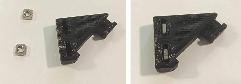
- M4x8 grub screw 6pcs (for optional spool holder and filament guide, and for door handle if needed )
- M4 square nut 5pcs (for optional spool holder and filament guide)
- M4x10–12 flat head wood screw 10pcs
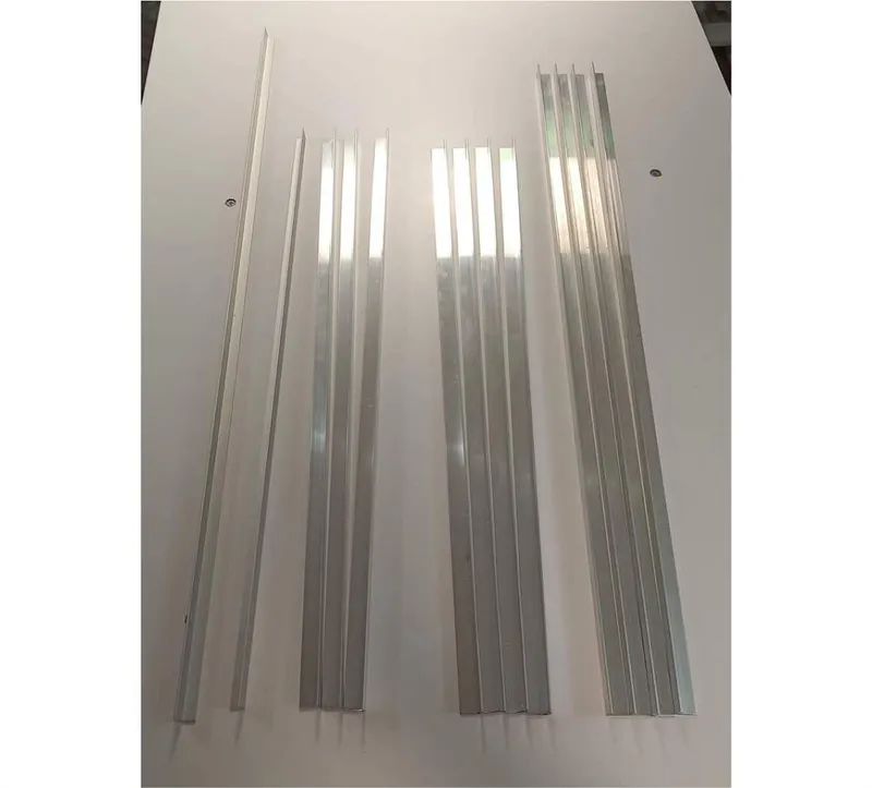
Aluminium "L" profile 15x15mm, 1.5mm thick:
- 535mm 4pcs
- 550mm 3pcs
- 650mm 4pcs
Aluminium "L" profile 15x10mm, 1.5mm thick:
- 550mm
- 730mm
- 520mm 2pcs
- 560mm 2pcs
Aluminium pipe 20mm diameter (for optional spool holder):
- 570mm
Plastic sheets:
- 587x572mm (top)
- 697x572mm 2pcs (left and right)
- 697x587mm (rear)
- 576x616mm (door)
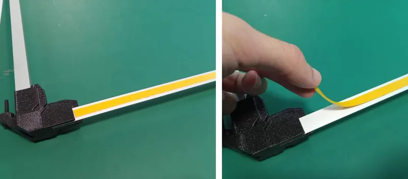
- double-sided tape (or other kind of adhesive)
- Window foam for the door seal
- Fan 120x120mm
- Fan switch
- Ventilation hose Ø10cm, length as needed
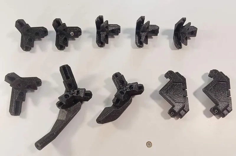
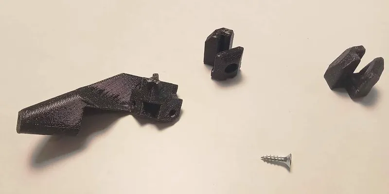
About 1.5kg of plastic for the printed parts:
- “corner singlepart” 5pcs
- “corner singlepart extended”
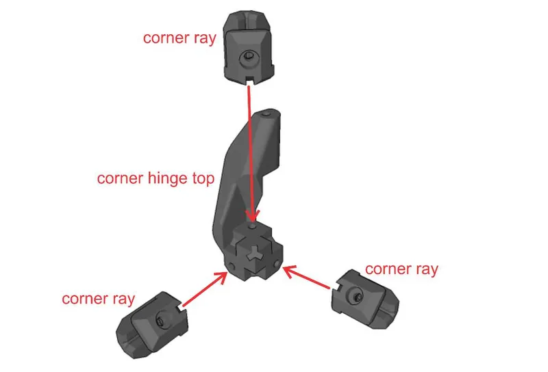
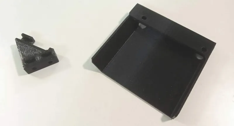
- “corner hinge top (multipart)”
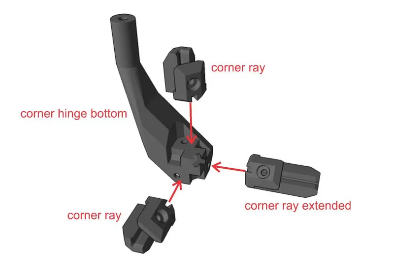
- “corner hinge bottom (multipart)”
- “diagonal connector” 2pcs
- “filament passage”
- “fan holder”
- “fan holder switch”
- “opening for cables”
- “spool holder L”
- “spool holder R”
- “spool holder spacer” 2pcs
- “filament guide partA”
- “filament guide partB”
- “filament guide partC”
- “filament guide rotary lock”
- “lock”
- “front panel, right”
- “front panel, middle, for MK2” or “front panel, middle, for MK4”
- “front panel, left”
- “door corner singlepart” 2pcs
- “door hinge top (multipart)”
- “door hinge bottom (multipart)”
- “door handle”
- “LCD extender for MK2” (L + R) and “LCD extender for MK2, cable clip”, or “LCD attachment for MK4”
Recommended to print in PETG, at least for the "corners", because PETG has better layer adhesion than PLA.
Assembly instructions
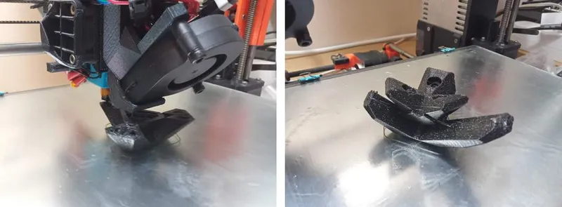
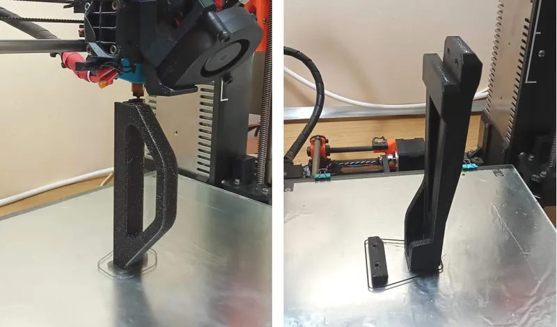
Step 1 - printing
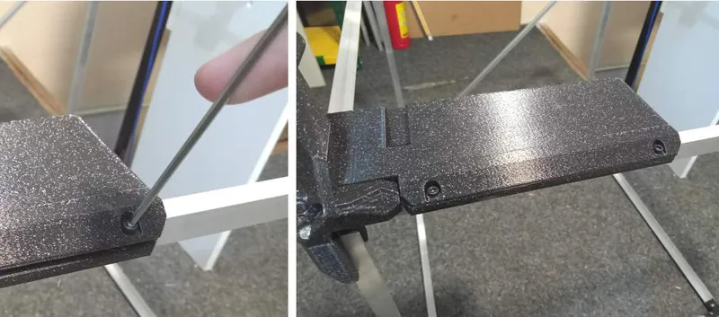
As said above, PETG is recommended filament. Also, print "corners" and "hinges" with many perimeters and a little hotter nozzle, to ensure strength and good layer adhesion.
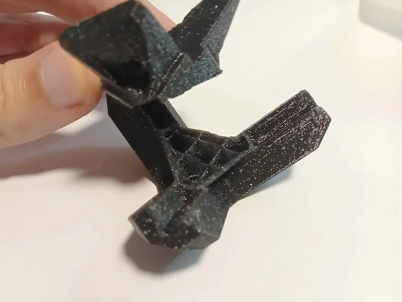
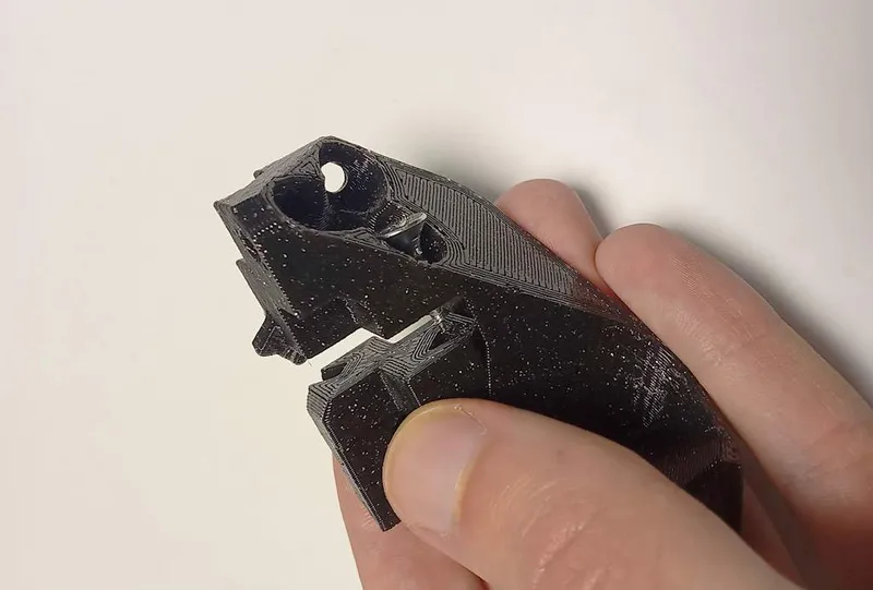
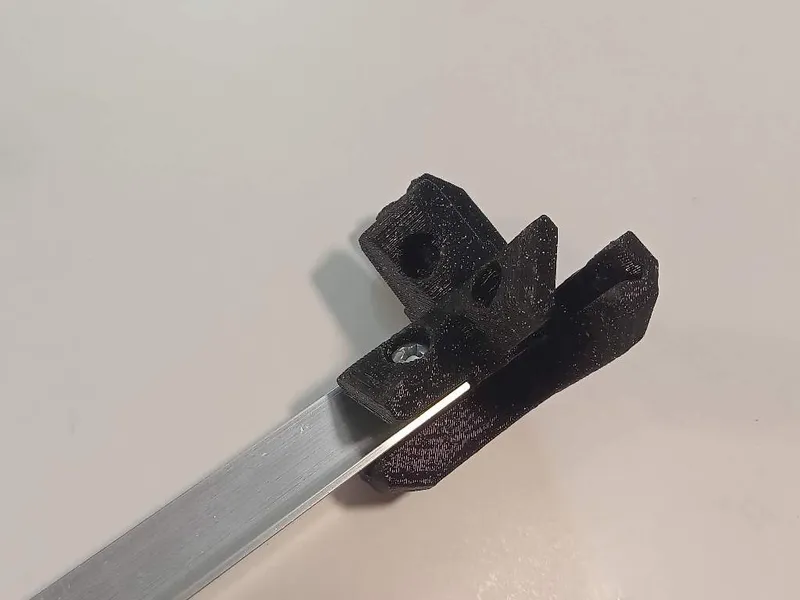
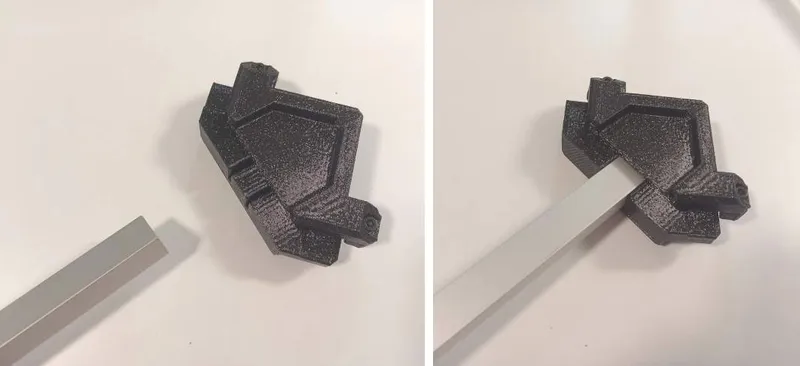
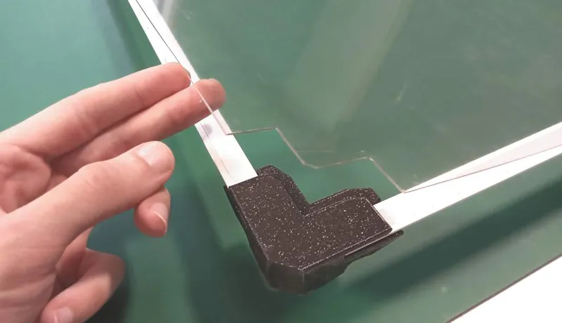
If printed with low number of perimeters, the corners can brake more easily, as seen in this image:
I've used 0.6mm nozzle and 5 perimeters (if printing with 0.4mm nozzle, increase extrusion width to 0.6mm, or increase the number of perimeters).
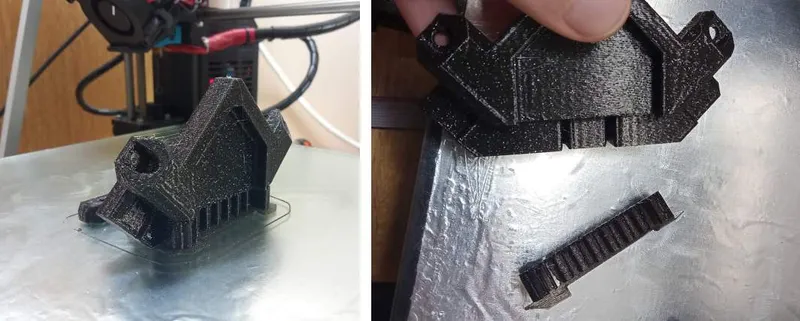
I'm providing alternative "corners", made from multiple parts and attached using wood screws M4x10, labelled "ALT" in the file name. These can be used instead of "corner singlepart" files. (This was how I first designed them, then I realized they can be printed in one piece. However if for some reason the "corner singlepart" can't be printed well, this is an alternative.)
Other parts (panels, etc.) can be printed with lower number of perimeters (e.g. 2) to save filament and time.
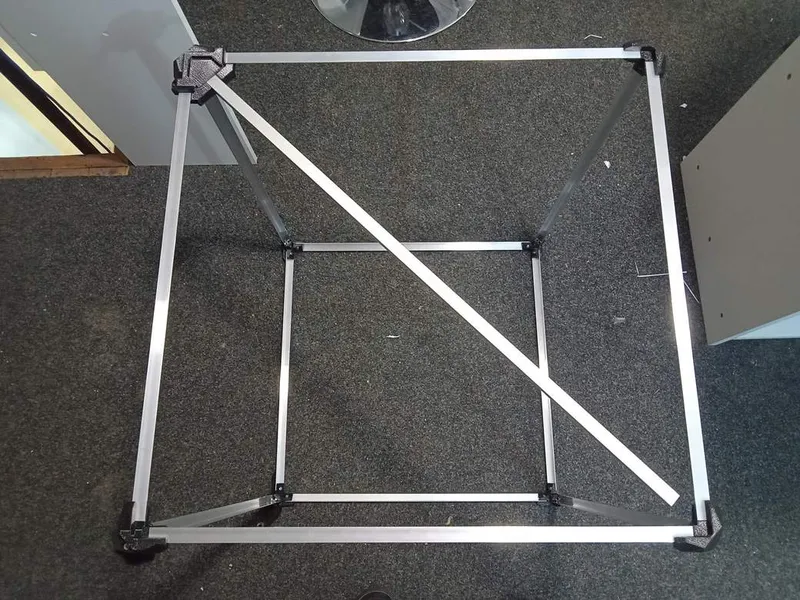
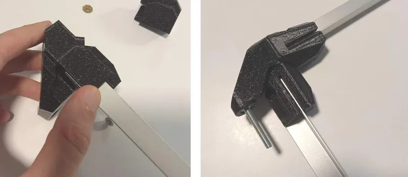
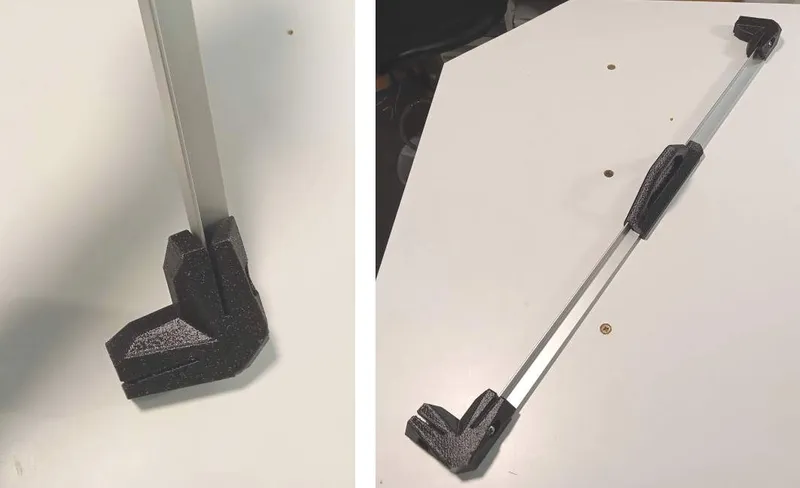
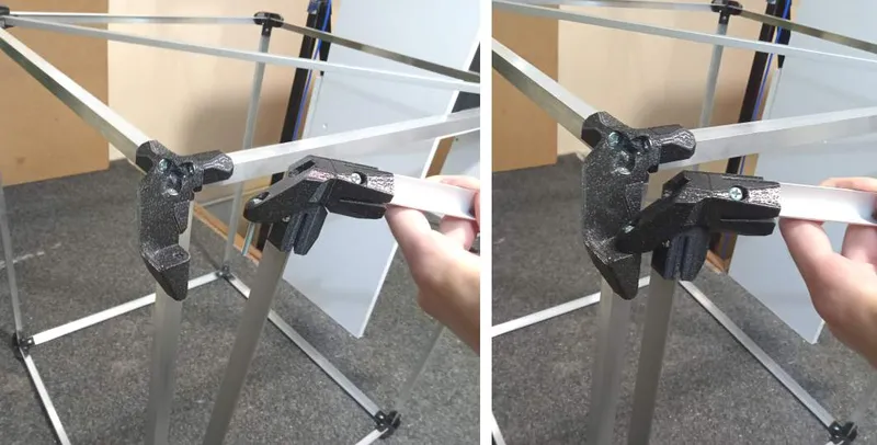
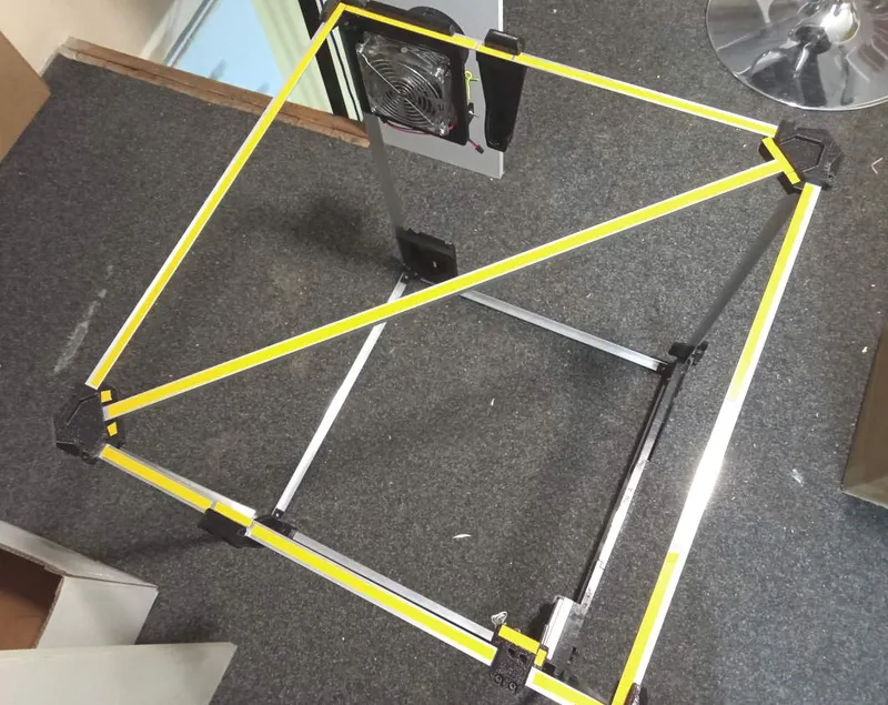
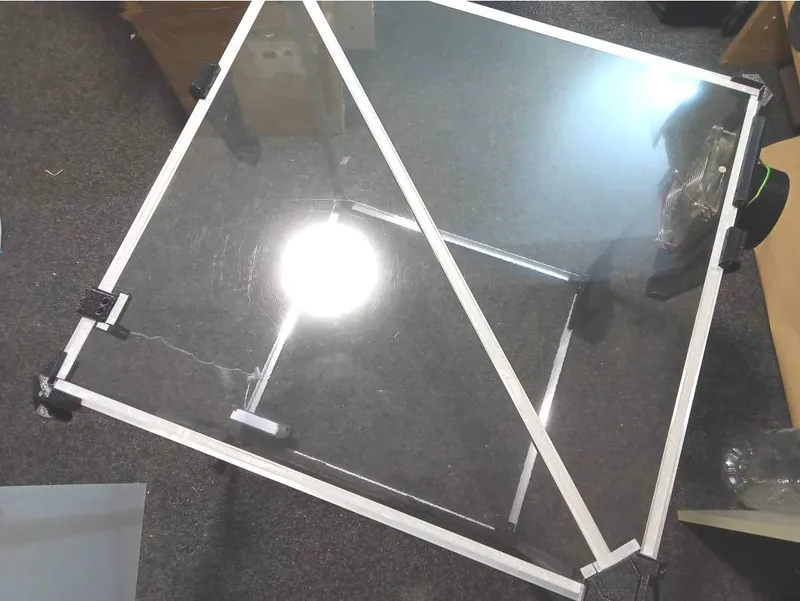
Step 2 - main frame
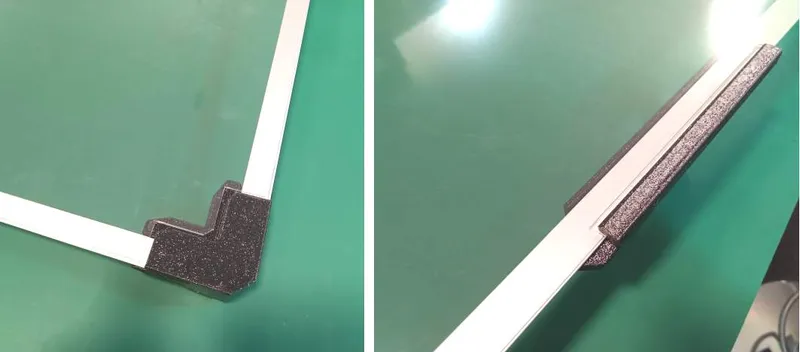
Cut the aluminium "L" profiles at appropriate lengths (see above).
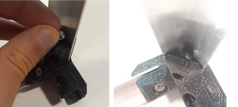
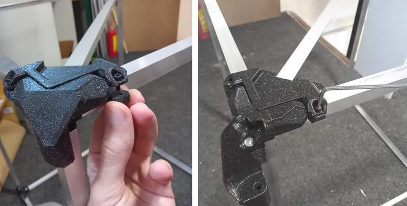
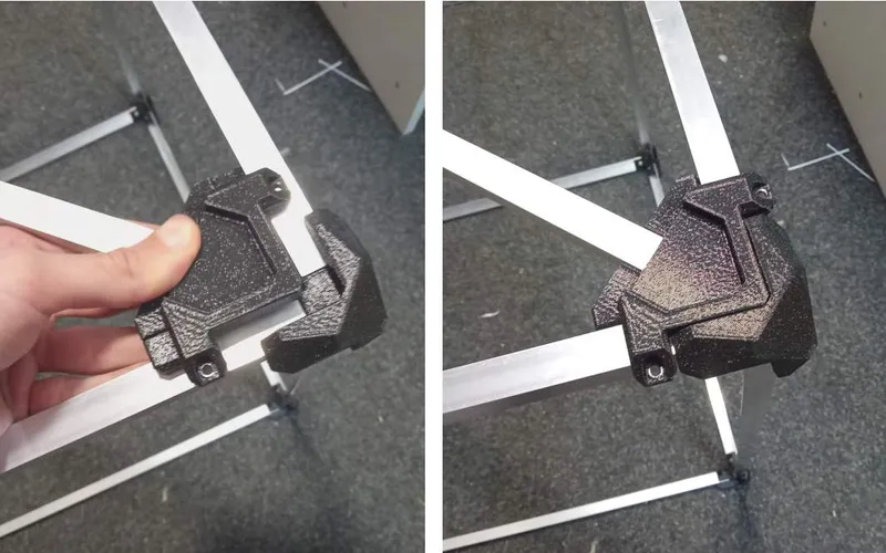
The image below shows placement of aluminium profiles and corner types:
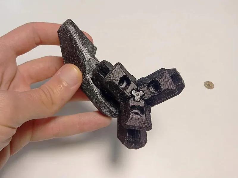
The hinges are assembled from 4 parts each, using wood screws M4x10 (or M4x12).
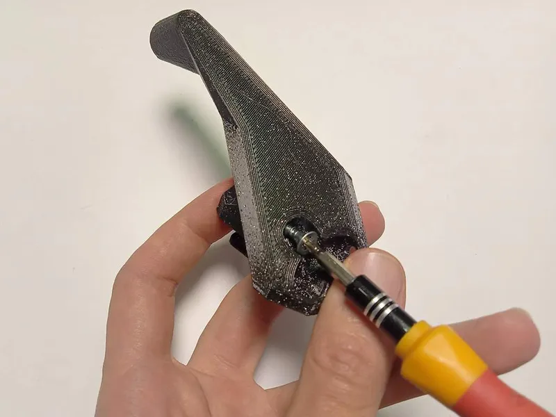
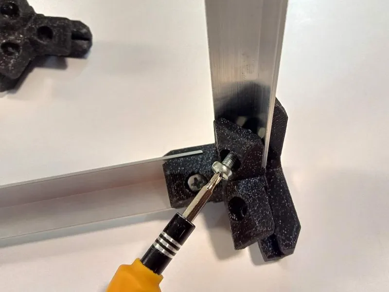
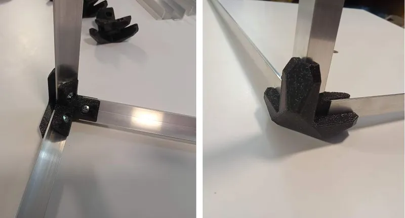
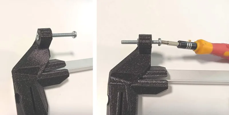
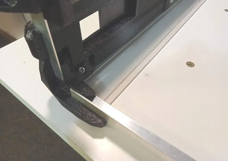
Start with one corner and insert one aluminium profile in a slot. Then insert an M4 hex nut and screw in M4x10 bolt. Then repeat the same for the two other sides.
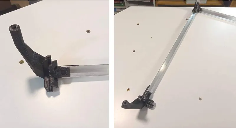
Attach "diagonal connectors" to the frame using M3x8 (or M3x6) bolts.
Step 3 - door frame
Placement of aluminium profiles and corners:
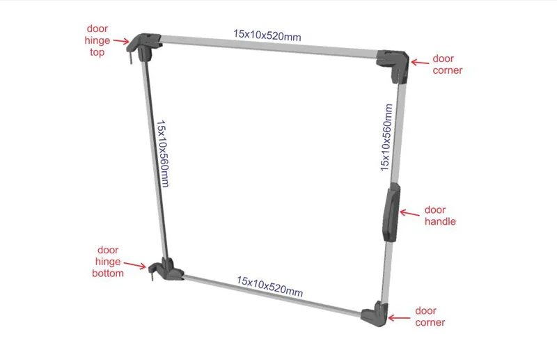
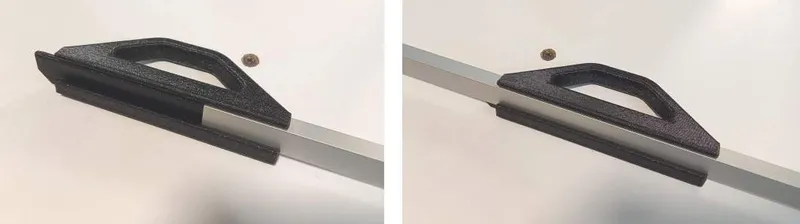
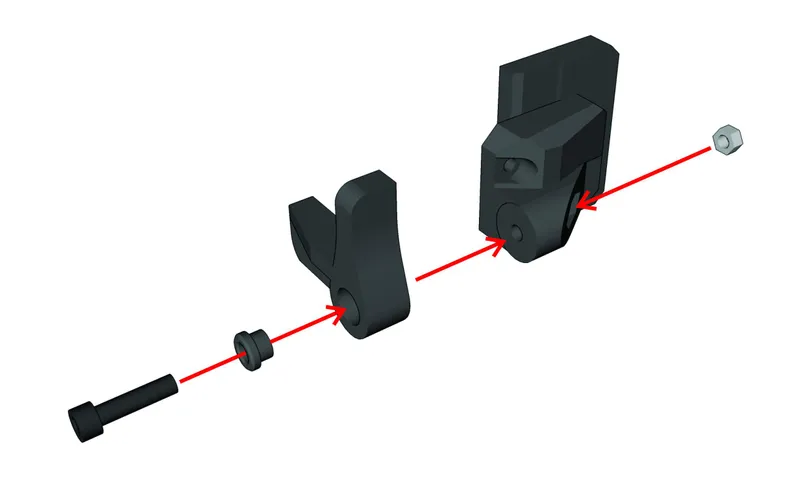
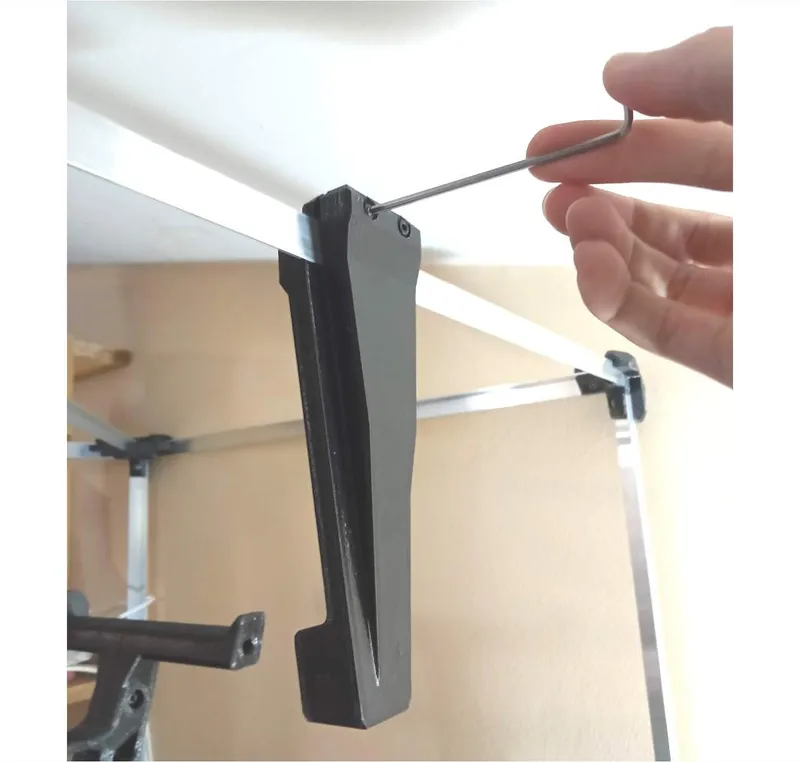
First slide the door handle onto one aluminium profile (560mm long). If needed, use M4 hex nut and M4x6–8 grub screw to hold it in place (I didn't need to, as friction holds it well).
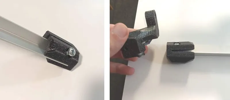
Insert aluminium profiles into hinge "rays", then connect the 3 hinge parts using wood screws M4x10 (or M4x12). Long bolts are used as hinge "pins" (M4x30 or M4x40 and M4 hex nuts).
Connect other corners to form a door frame using M4x10 bolts and M4 hex nuts.
Step 4 - attachments
Positions of attachments (for my setup, if changing something, also change the shape of plastic sheets and adjust whatever else if necessary):
Slide "front panel, left", "front panel, right", "opening for cables", "filament passage" and "lock" onto the frame and attach them using M3x8 (or M3x6) bolts.
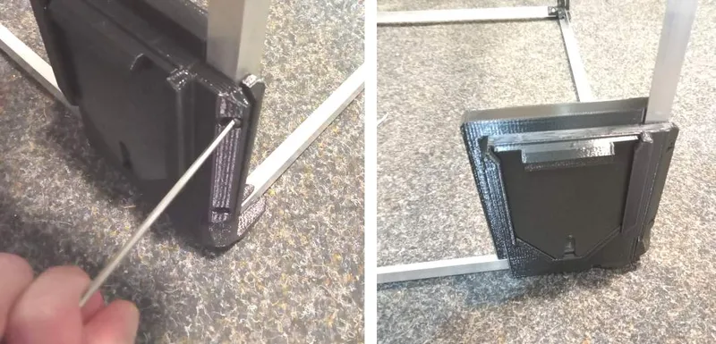
The "lock" hinge is attached with M4x16 bolt and M4 hex nut.

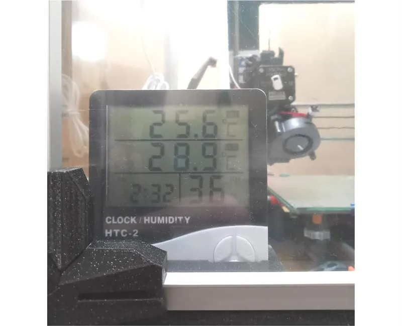
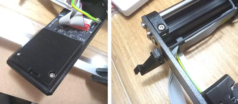
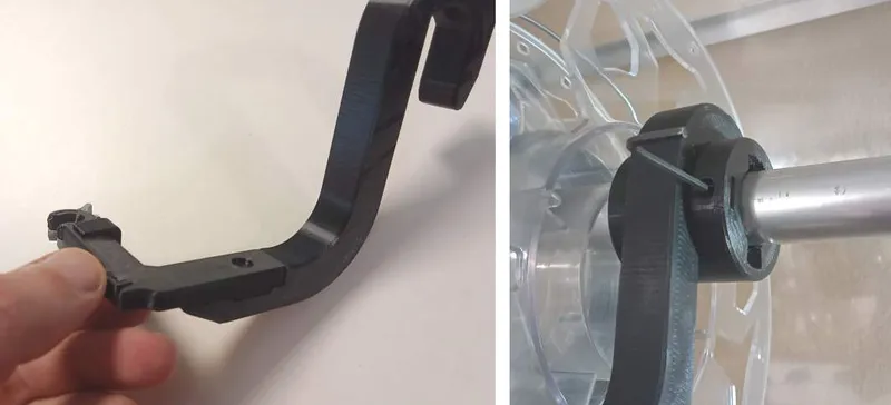
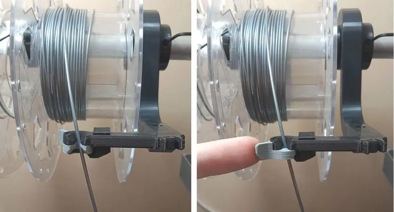
"Filament passage" can be used for printing with filament located outside the enclosure (guided through PTFE tubes). It is also used to hold a thermistor for monitoring temperature in the top part of the enclosure, while the thermometer is placed in a slot in the "front panel, left".
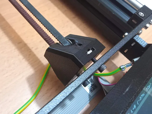
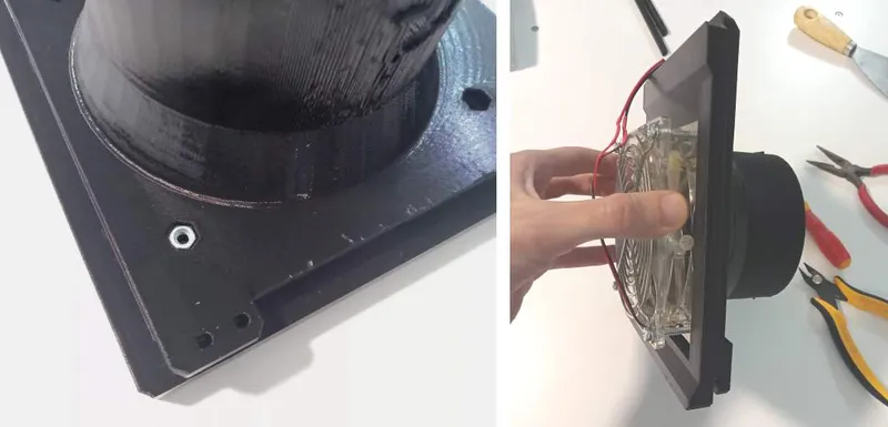
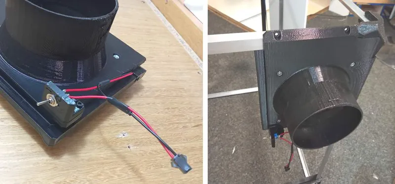
Attach a fan (120x120mm) to the "fan holder" using M4x35 bolts and M4 hex nuts. Attach "fan holder switch" using M3x8 bolts. Attach the fan holder to the frame using M3x8 (or M3x6) bolts.
Optional: attach "spool holders" using M3x12 bolts.
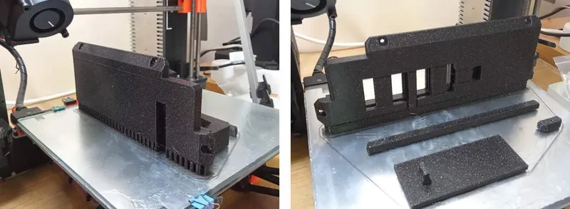
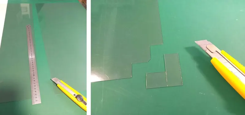
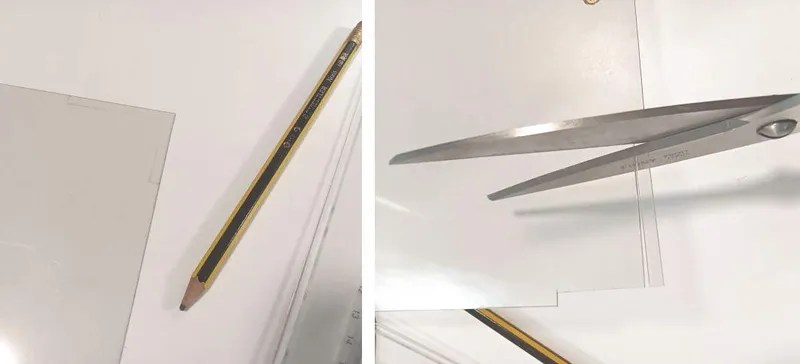
Step 5 - plastic sheets
Cut the plastic sheets in appropriate sizes and shapes, see .svg files. Adjust the cutouts if changing the position of attachments.
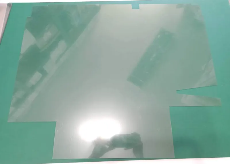
Use double sided tape (or some other adhesive) to stick the plastic sheets onto the frame. This is a tricky part, as the frame is not holding its exact shape without the plastic sheets, therefore it's not an easy task to precisely stick them in place. I don't have a good advice for this, just plan carefully how to do it.
On the bottom side, if the enclosure is larger than the table/shelf, a narrow piece of plastic sheet can be placed to cover the opening.
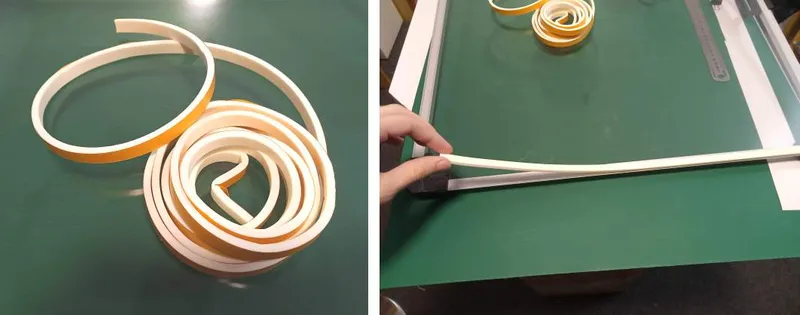
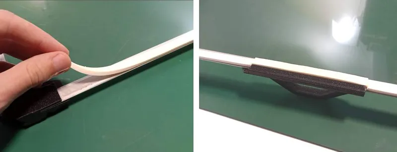
Use window foam to close the gap between the door and the frame.
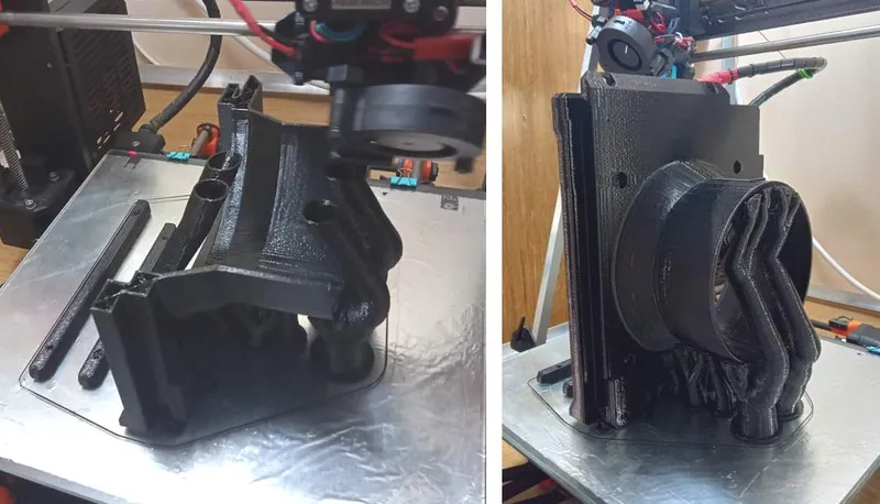
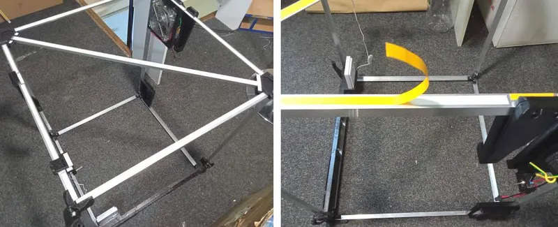
Step 6 - ventilation
Attach ventilation hose onto the enclosure and lead it out the window or somewhere.
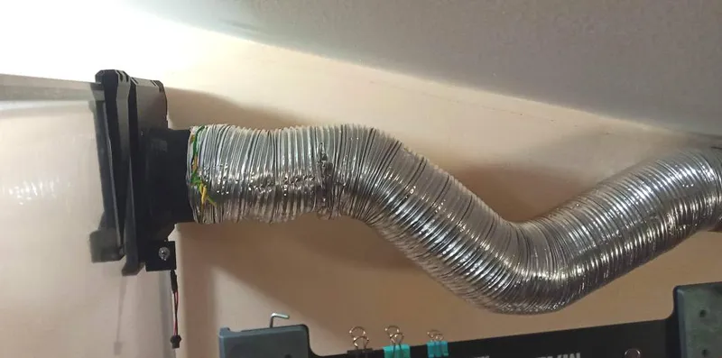
As said at the beginning, it's probably better to put the fan on the other end of the hose (on the window), but it was simpler this way for me, and hopefully it's good enough.
Step 7a - printer LCD - Prusa MK2
Detach the LCD from the printer and attach it on the "LCD extender for MK2". The cables leading to the LCD must have enough length, make sure to guide the cables to allow as much slack at the front of the printer.
Put the printer inside the enclosure, with the LCD sticking outside. Make sure to position it precisely to align the LCD with the opening on the front. Insert "front panel, middle, for MK2" on top of the LCD extender.
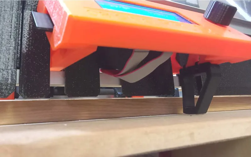
Step 7b - printer LCD - Prusa MK4
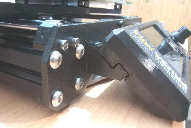
Detach the LCD from the printer and unscrew the left LCD support. Route the LCD cables to create as much slack at the front as possible.
Screw in the "LCD attachment for MK4", the larger piece on the LCD, and the smaller piece on the printer frame (reuse the bolts and square nuts from the original LCD support). The smaller piece allows returning the LCD to the normal position, by using only two bolts (or just one, as it's enough) on the right LCD support.
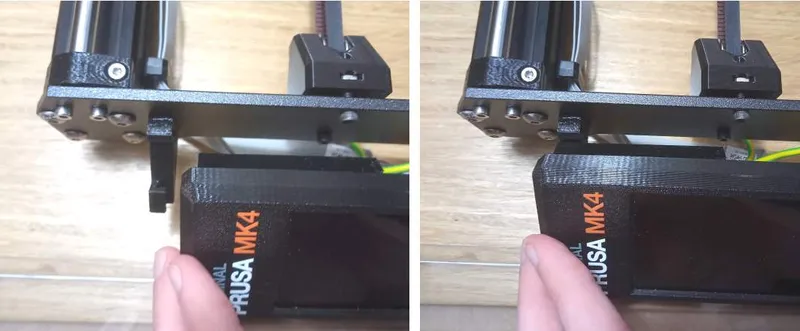
Put the printer inside the enclosure and position it so that the print bed does not collide with the enclosure. Place the LCD outside of the enclosure, with the cables placed on the left side, to allow "front panel, middle, for MK4" to be inserted in the enclosure frame.
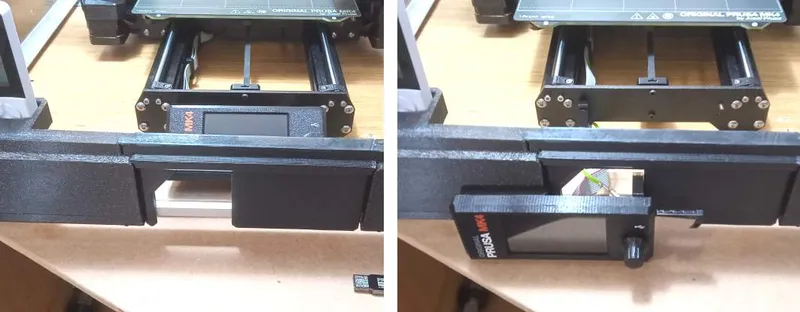
This design for MK4 is not really optimal, as the LCD just sits in front of the enclosure, not attached to anything. The problem is that the cables aren't long enough to allow optimal placement. I decided that this is good enough for my setup, as I'll primarily use the enclosure for the MK2, and rarely for MK4.
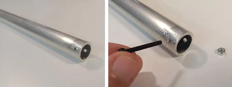
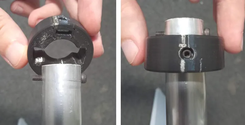
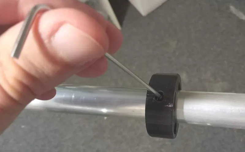
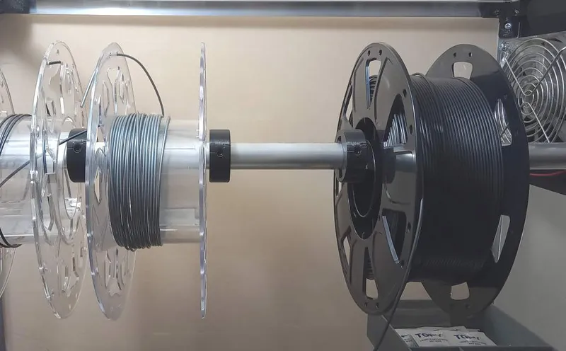
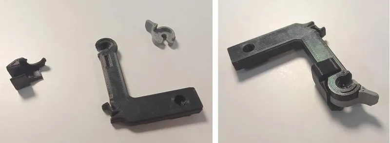
Step 8 - spool holder pipe (optional)
Cut aluminium pipe to 570mm. Drill holes on the ends using the provided "drill guide" (3D printed).
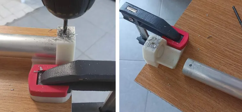
Screw in M3x25 with M3 hex nuts in both holes.
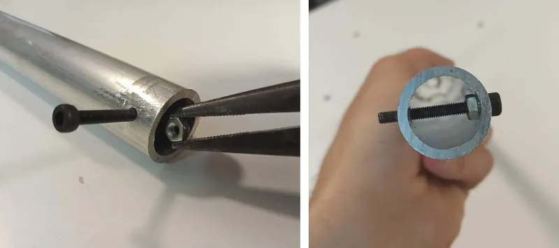
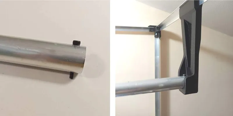
Prepare "spool holder spacers" by inserting M4 square nut and M4x8 grub screw. Slide the spacers on the pipe and tighten the grub screws.
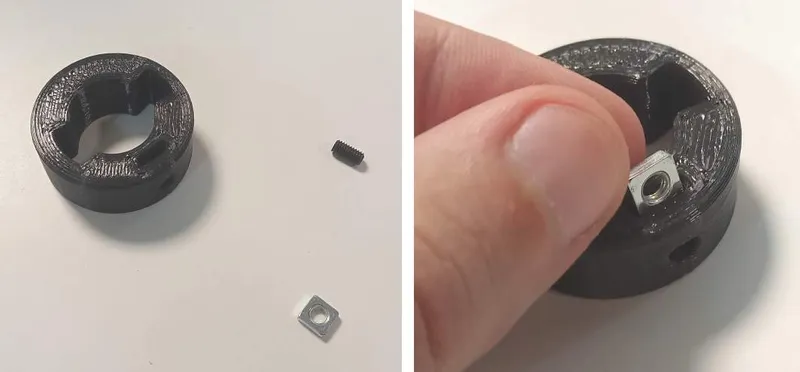
Assemble filament guide using M3x10 bolt + M3 hex nut, and M4x8 grub screw + M4 square nut.
___________________________________________________________
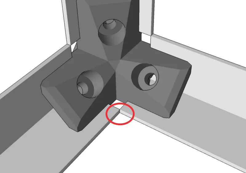
Files adjusted for aluminium "L" profiles 20x20mm and 20x10mm (instead of 15x15mm and 15x10mm) are in a separate folder. Those files that are not changed are not repeated.
It might be needed to file down/cut corners of the aluminium profiles, because they would meet like this:
Tags
Model origin
The author marked this model as their own original creation.